Description
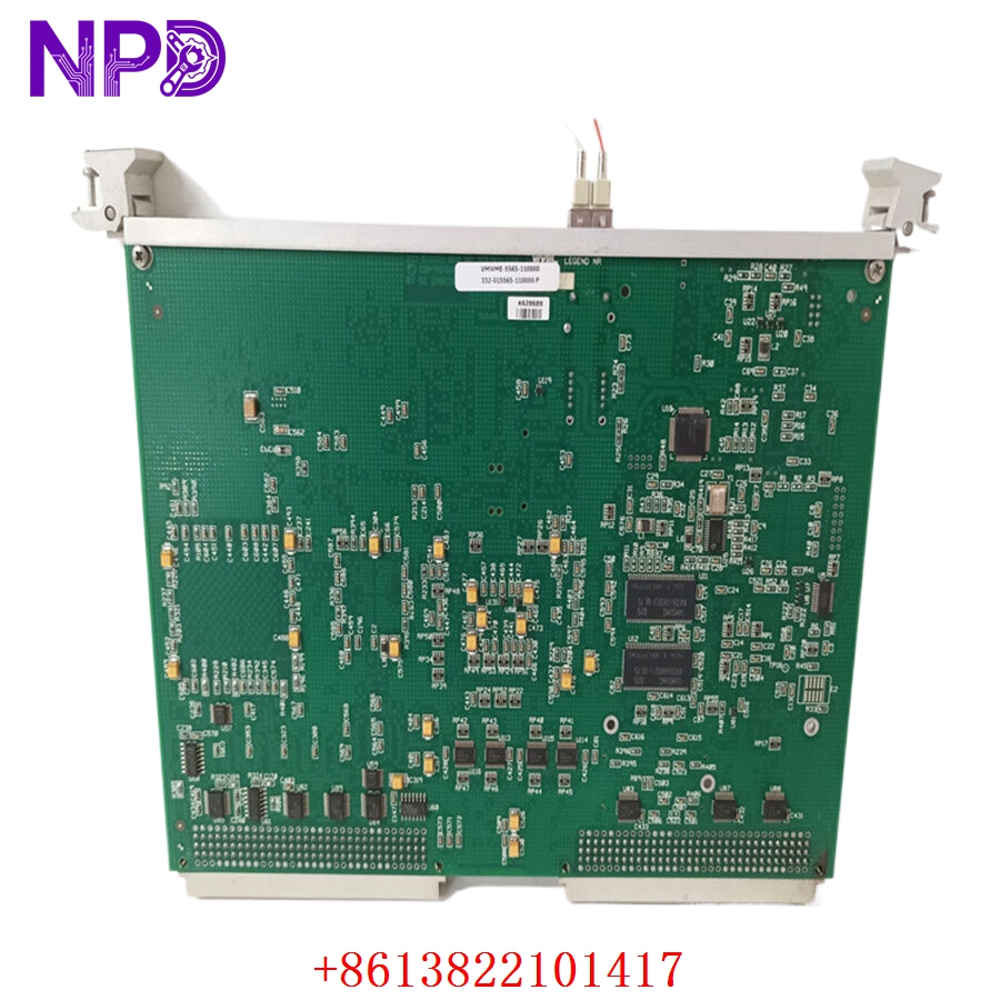
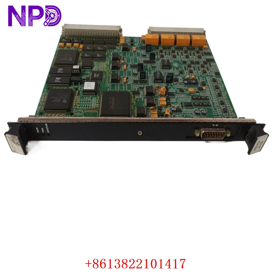
- Model: IS200VSVOH1BDC (Manufacturing Identifier: MRP643486)
- Brand: General Electric (GE)
- Series: Speedtronic Mark VI Turbine Control System
- Core Function: 4-Channel Electrohydraulic Servo Valve Control Card (VSVO)
- Condition: Brand New Surplus (Original authentic warehouse stock, zero run-time hours)
- Product Type: VME Bus Core Control Card
- Key Specs: 4 Servo Channels | Up to 3 LVDT/LVDR sensors per channel | Bi-directional current output | Freq Range 2 Hz–14 kHz
- Servo Loop Architecture: Natively manages 4 independent electrohydraulic servo channels. It executes loop control algorithms internally using an onboard Digital Signal Processor (DSP), minimizing VME backplane calculation lag.
- Position Feedback Compatibility: Supports up to three Linear Variable Differential Transformers (LVDTs) or Linear Variable Differential Reluctances (LVDRs) per servo channel with software-configured voting algorithms (Median Select, High Select, or Low Select).
- Current Driver Output: Provides bi-directional current outputs engineered to directly modulate the coils of 2-coil or 3-coil industrial servo valves.
- Pulse Rate Feedback: Built-in high-resolution pulse rate inputs operating over a 2 Hz to 14 kHz frequency range, primarily optimized for flow divider feedback within close-coupled fluid loops.
- Speed Sensor Interfacing: Features direct connection paths for both active (magnetic proximity) and passive (variable reluctance) magnetic speed sensors.
- Backplane Integration: Form-factor optimized for standard VME processor racks, utilizing high-density, latching-type edge connectors to link with TSVO terminal blocks via J3 and J4 connections.
- Front Panel Interfacing: Features an integrated J5 diagnostic cable interface along with 3 clear operational tracking LEDs (RUN, FAIL, STATUS).
GE MRP643486 IS200VSVOH1BDC
GE MRP643486 IS200VSVOH1BDC
Installation & Configuration Guide
Phase 1: Pre-Installation (Estimated Time: 15 minutes)
⚠️ Safety Critical Warning:
- The IS200VSVOH1BDC directly controls fuel and steam throttle valves. Any unexpected signal fluctuations during hot extraction can lead to immediate turbine overspeed, mechanical surging, or an uncontrolled emergency shutdown. Never swap this module while the turbine is online.
- Complete electrical lockout protocols must be verified for the target VME rack sector before hardware handling.
Required Tools & Protective Gear:
- Properly grounded anti-static ESD wrist strap
- Insulated slot-head card extraction handle tool
- Process calibration loop analyzer
- Form-fit anti-static storage envelope
Phase 2: Removal (Estimated Time: 10 minutes)
- Power Down the Rack: Shut off the primary system breaker powering the VME processor rack assembly. Verify that all front-panel LEDs across neighboring cards in the rack have gone dark.
- Disconnect Front-Panel Links: Gently unlatch and pull the J5 diagnostic connector profile free from the front sheet metal.
- Release Ribbon Connectors: Navigate to the lower sector of the rack layout and carefully unlatch the secure cabling links paired with the TSVO assembly at the J3 and J4 connection boundaries.
- Extract the Module: Unlock the top and bottom injector/ejector tabs on the VSVO card. Slide the module cleanly straight out of the rack chassis track rails. Place it immediately inside an anti-static shield container.
Phase 3: Installation (Estimated Time: 15 minutes)
- Jumper & Artwork Check: Lay the new surplus IS200VSVOH1BDC board down onto a static-safe surface. Ensure that all revision jumpers and hardware artwork configurations perfectly match your original plant layout specification sheets.
- Slide Card into Rack: Guide the card edge into the dedicated slot tracks. Push smoothly until the board’s high-density backplane contacts seat firmly into the VME base infrastructure.
- Lock Faceplate Latches: Snap the upper and lower injection handles inward to fully lock the module frame in place. Tighten any faceplate hardware to roughly 0.4 N·m.
- Re-engage Field Cables: Reattach the latching-type cables back into the J3, J4, and J5 headers, ensuring the side retention mechanisms click shut securely to prevent vibration walk-out.
Phase 4: Power-On & Loop Commissioning (Estimated Time: 30 minutes)
The Validation Protocol:
- Restore primary operational power back to the VME rack.
- Analyze Initial Diagnostics: Verify the RUN LED glows steady green. Ensure the FAIL indicator remains completely off after the initial boot-up sequence passes.
- Execute LVDT Calibration: Open your engineering workspace on the HMI terminal. Run the manual stroke calibration loop routine for the paired servo valves.
- Check that the position feedback tracking via LVDT registers accurately within specified engineering units, and ensure the AC excitation signals are balanced across the loop.
- Once positional tolerances lock within normal parameters, transition the loop algorithm out of maintenance override back into service.
- Archive the new module serial identifier, firmware block revision records, and technician parameters inside your local automation maintenance database.
Frequently Asked Questions (FAQ)
Q1: What specific function does the VSVO board perform in a Mark VI system?
A: The VSVO (Servo Control Board) acts as the critical positioning link between the digital software control logic and the physical fuel or steam regulation mechanisms. It takes position demands from the master controller, compares them to real-time LVDT valve feedback signals, and internally runs loop control calculations to send a bi-directional current output out to the electrohydraulic servo valve coils, regulating mechanical fuel or steam stroke.
Q2: What is the significance of the “BDC” tag at the tail of the part number?
A: In GE’s component control tracking, IS200VSVOH1BDC represents a specific revision layer built over the base design framework. The letters B, D, and C denote specific production-lot component optimizations, minor trace engineering modifications, and hardware artwork updates implemented to extend lifecycle reliability and minimize signal thermal drift. This board acts as a direct drop-in replacement for any earlier version H1 baseline positions.
Q3: Why is a minimum of two LVDT/LVDR sensors recommended when deploying this board in TMR systems?
A: In Triple Modular Redundant (TMR) applications, high-reliability voting logic is crucial. Each active feedback path requires an independent AC excitation source. Utilizing at least two (and ideally three) LVDT feedback tracks allows the internal DSP logic on the IS200VSVOH1BDC to execute median, high, or low select algorithms. This configuration ensures that if one feedback sensor fails, the remaining loops can seamlessly maintain valve control without causing a turbine trip.