
Description
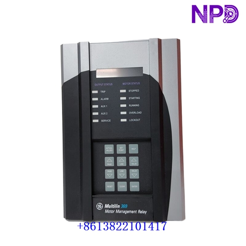
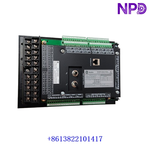
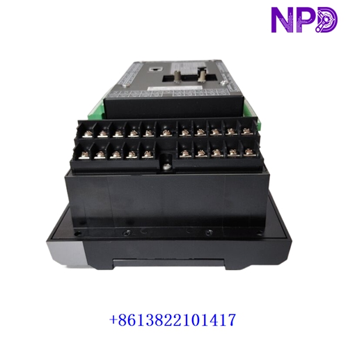
The GE Multilin 369-H1-R-M-F-E-H-E is a microprocessor-based digital motor protection and management relay engineered to safeguard low- and medium-voltage three-phase AC motors. It provides comprehensive thermal modeling, short-circuit protection, current unbalance monitoring, and advanced operational data logging.
| Parameter | Specification |
| Brand | GE Grid Solutions / Multilin |
| Model Series | 369 Motor Management Relay |
| Full Catalog Number | 369-H1-R-M-F-E-H-E |
| Control Power (H1) | High Range: 50–300 VDC / 40–265 VAC (50/60 Hz) |
| RTD Inputs (R) | Built-in 12-channel RTD temperature inputs (Pt100, Cu100, Ni120, Ni100) |
| Metering Package (M) | Advanced electrical metering (V, A, kW, kVAR, kVA, kWh, MWh, PF, Hz) + 3 additional analog outputs |
| Communications (F) | Optional Fiber Optic Port (in addition to standard front RS-232 and rear RS-485 Modbus RTU ports) |
| Harsh Environment (E) | Conformal coating applied to internal circuit boards for protection against moisture and corrosive agents |
| Diagnostics (H) | Enhanced diagnostics package, expanded event recording, and security audit trail |
| Enclosure / Mounting | Compact non-drawout metal case with integrated display/keypad interface |
Key Protective & Monitoring Functions
- Thermal Overload Protection (49): Dynamic thermal modeling that incorporates phase current, current unbalance, and real-time RTD winding feedback.
- Fault Detection: Overcurrent (50P/50G), short-circuit, mechanical jam (48), load-loss/undercurrent (37), and sensitive ground fault detection.
- Start-Up Control: Starts-per-hour limitations, minimum time between starts, locked rotor protection, and backspin detection.
- Data Recording: High-resolution event recorder, waveform capture (oscillography), and a dedicated Motor Health Report.
First-Run Inspection Checklist
- ☑ Physical Integrity & Coating Check
Inspect the enclosure, rear terminals, and display lens for shipping damage. Verify that the conformal coating indicator matches plant environmental requirements.
- ☑ Control Power Verification
Confirm that the auxiliary source voltage aligns with the H1 high-range power supply limits (40–265 VAC / 50–300 VDC) using a multimeter prior to energization.
- ☑ CT/VT and RTD Wiring Check
Ensure phase current transformers, optional voltage transformers, and the 12-channel RTD sensors are correctly wired to their designated terminal blocks before system commissioning.
Routine Maintenance & Servicing
- 🛠 Thermal & Environmental Audit
Periodically review internal relay health metrics and ensure switchgear panel cooling keeps ambient temperatures within the -40°C to +60°C operating range.
- 🔌 Communication Link Inspection
Check the front RS-232 port, rear RS-485 loops, and the fiber optic interface (F) connections for secure termination and stable packet transmission.
Troubleshooting & Common Issues
- ⚠️ Thermal Model Lockouts
If the motor is prevented from restarting, check the thermal capacity estimation via the front display or software to verify if the motor is still within its calculated cooling time constant period.
- ⚠️ RTD Open/Short Alarms
If an RTD alarm trips unexpectedly, inspect physical sensor wiring continuity and verify that the correct RTD type (Platinum, Nickel, or Copper) is selected in the software configuration.
Safety Precautions
- 🔐 Qualified Personnel Only
Programming, testing, and maintenance must be performed exclusively by certified electrical technicians familiar with medium-voltage motor control systems.
- ⚠️ Current Transformer Safety
Never leave CT secondary circuits open while the primary motor feeder is energized. Always short-circuit CT secondaries prior to servicing internal wiring or swapping hardware.
Frequently Asked Questions (Q&A)
- ❓ Q1: What does the ‘M’ designation signify in this specific part number?
A: The M code indicates that the optional metering package is installed, providing high-accuracy power parameters (kW, kVAR, kVA, PF, kWh) alongside extra configurable analog outputs.
- ❓ Q2: How can configuration files and event logs be extracted from the relay?
A: Parameters can be managed locally via the front-panel keypad and display or remotely using setup software through the front RS-232 port, rear RS-485 network, or the fiber-optic communication port.