Description
- Model: SR469-P5-HI-A20-E
- Brand: GE Multilin
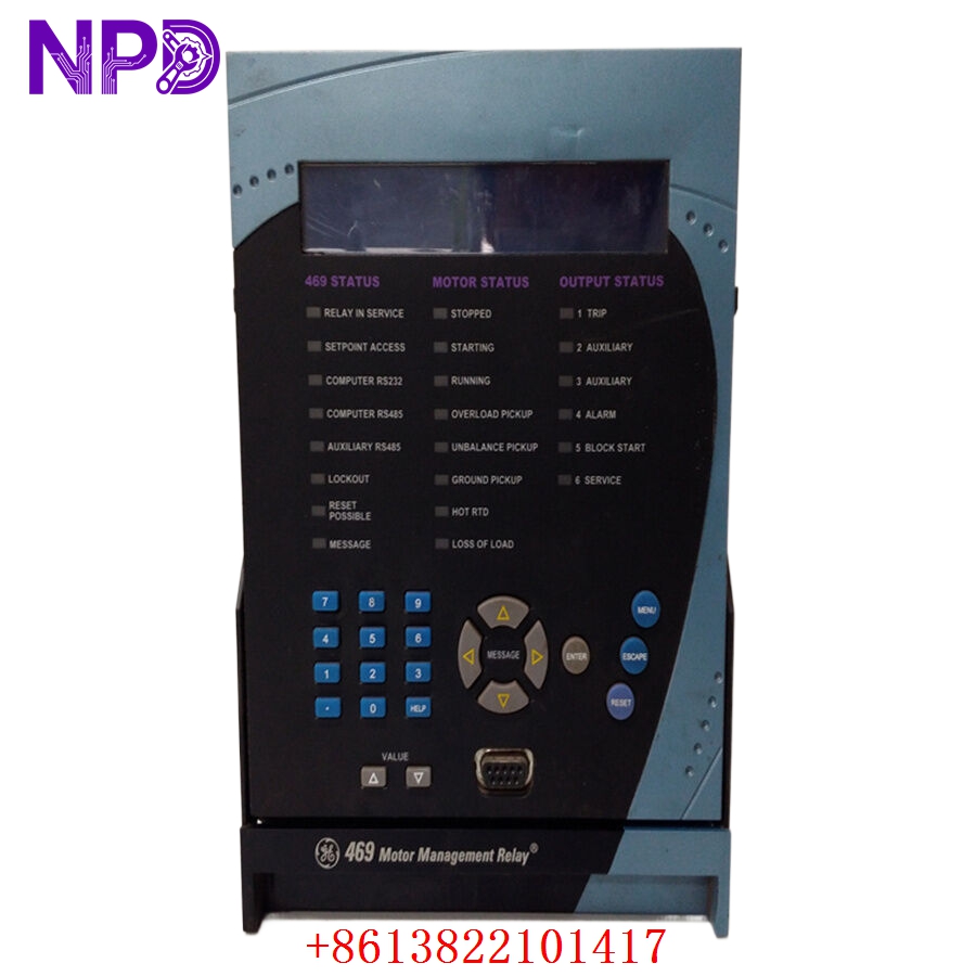
- Series: 469 Motor Management Relay
- Core Function: Comprehensive protection, control, and monitoring for medium-to-large horsepower motors.
- Condition: Brand New Surplus (Original New), Non-refurbished
- Type: Digital Protection Relay
- Key Specs: 5A Phase CT Secondary High-Voltage Control Power Enhanced Graphics Display
Understanding the suffix of your SR469-P5-HI-A20-E is critical for compatibility:
- P5: 5 Amp Phase CT Secondaries (Standard for most industrial CTs).
- HI: High-Voltage Control Power (Range: 88–300 VDC or 70–265 VAC).
- A20: Enhanced Display (vacuum fluorescent) with 4–20 mA Analog Outputs.
- E: Enhanced Faceplate with Additional Features/Communications.
GE SR469-P5-HI-A20-E-H
GE SR469-P5-HI-A20-E-H
GE SR469-P5-HI-A20-E-H
Key Technical Specifications
- Protection Functions: Thermal Model, Stalling, Phase Reversal, Under/Overvoltage, Ground Fault, Bearing Overtemperature (RTD).
- Inputs:
- 6 RTD Inputs (100 Ohm Platinum, 100 Ohm Nickel, 120 Ohm Nickel, or 10 Ohm Copper).
- 4 Assignable Digital Inputs.
- Outputs:
- 4 Programmable 4–20 mA Analog Outputs.
- 6 Output Relays (Trip, Aux, Alarm, Service).
- Communications: RS232 (Front), RS485 (Rear), Modbus RTU Protocol.
- Monitoring: Current, Voltage, Power (kW, kVAR, kVA), Energy (MWh), Power Factor.
- Event Recorder: Up to 128 events stored in non-volatile memory.
- Waveform Capture: Oscillography for fault analysis.
Installation & Configuration Guide
Phase 1: Preparation (20 Minutes)
⚠️ Safety First:
- Ensure the motor is locked out and the high-voltage switchgear is de-energized.
- The SR469 involves Current Transformer (CT) circuits. Never open-circuit a live CT secondary, as it creates life-threatening high voltages.
- Verify your control power matches the “HI” rating (typically 120/220V AC/DC).
Tools & Protection:
- ESD wrist strap.
- 1/4″ Nut driver or screwdriver for the terminal blocks.
- Laptop with GE EnerVista 469 Setup software.
Phase 2: Removal & Mounting (15 Minutes)
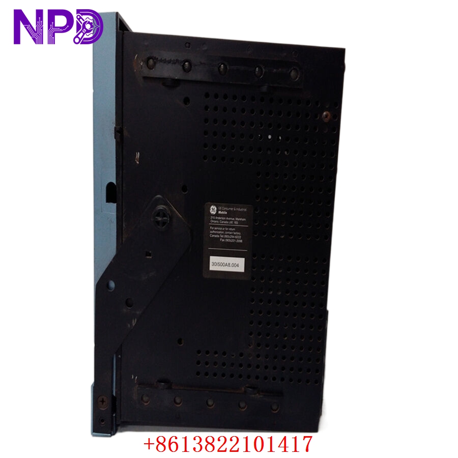
- Draw-out Mechanism: The 469 is a “draw-out” relay. Unlock the handle and pull the relay chassis out of the cradle.
- Mounting: If installing a new unit, ensure the panel cutout is standard for the SR469 frame.
- Cradle Check: Inspect the finger-connectors at the back of the cradle for any signs of pitting or overheating.
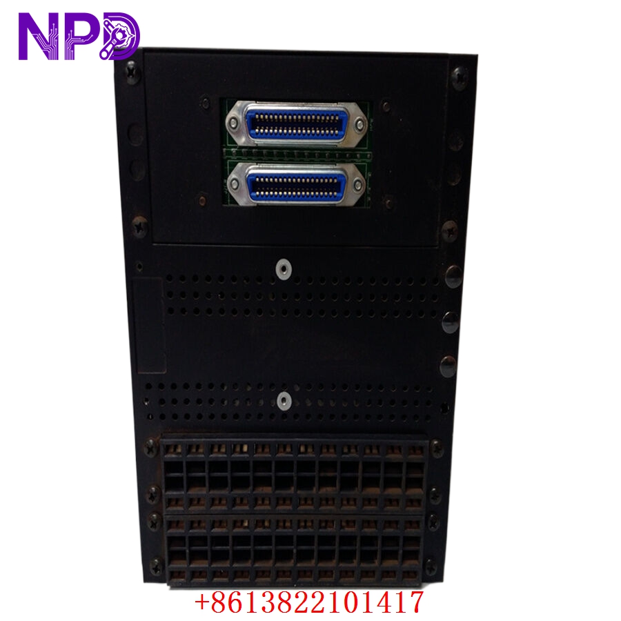
Phase 3: Wiring (30 Minutes)
- CT Connections: Land your 5A Phase CT wires on the P5 terminals. Ensure polarity is correct for proper power measurement.
- RTDs: Connect motor bearing and winding RTDs. If using 3-wire RTDs, ensure lead-length compensation is properly wired.
- Grounding: Ensure the relay case is solidly grounded to the panel ground bus to prevent electromagnetic interference (EMI).
Phase 4: Commissioning (45 Minutes)
- Firmware Check: Power up the relay. Check the firmware version on the display. It should match your project file version in EnerVista.
- Settings Upload: Connect via the front RS232 port. Upload the motor data (FLA, Service Factor, Locked Rotor Current, etc.).
- Thermal Model Test: Perform a “Secondary Injection Test” if a test set is available to verify the trip curve.
- Analog Outputs: Verify the 4–20 mA signals reach your DCS or PLC correctly.
Customer Cases & Industry Applications
Case 1: Mining Conveyor Motor Protection
Situation: A large gold mine used GE SR469 relays on their primary crusher motors. A faulty relay caused a nuisance trip, stopping production for 4 hours. Task: Replace the failed unit with a factory-new spare to ensure the motor’s thermal model is accurately tracked. Action: We provided a New Surplus SR469-P5-HI-A20-E. Result: The enhanced display (“A20”) allowed the operators to see real-time thermal capacity remaining, allowing them to optimize the crusher load without risking a trip.
Case 2: Oil & Gas Pumping Station
Situation: An aging pump station was upgrading from electromechanical relays to digital protection. Task: Standardize on the GE Multilin 469 series due to its robust history in harsh environments. Action: The customer purchased a batch of SR469-P5-HI-A20-E units. Result: By using the “HI” power supply version, they were able to use the station’s existing 125VDC battery bank for control power, eliminating the need for additional transformers.
Frequently Asked Questions (FAQ)
Q: Can I replace a P1 relay with this P5 relay? A: No. The P5 is for 5A CTs, and the P1 is for 1A CTs. Using a P5 relay with 1A CTs will result in the relay “seeing” only 20% of the actual current, which will lead to a motor burnout without a trip.
Q: What is the “A20” option vs “A1”? A: The A20 provides four 4–20 mA analog outputs, whereas the A1 only provides one. The A20 is preferred for modern plants that want to send Current, Voltage, Power, and Temperature data simultaneously to a PLC/DCS.
Q: Is the battery included? A: Yes, but for “New Surplus” units that have been in storage, we recommend checking the internal lithium battery voltage. We can provide a fresh battery upon request to ensure your event logs remain intact during power outages.
Q: Is this relay compatible with the older GE 269 or 369 series? A: It is a significant upgrade. While it can replace the functions of a 269/369, the wiring and panel cutout are different. We recommend the SR469 for its superior thermal modeling and diagnostic capabilities.