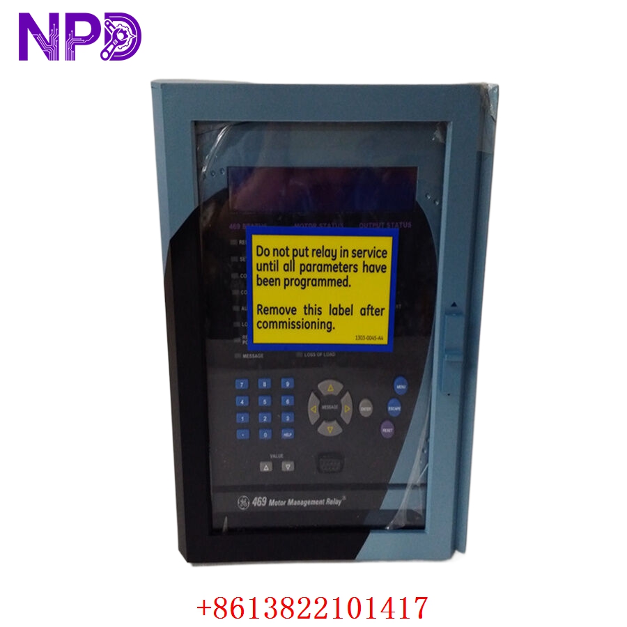
Description
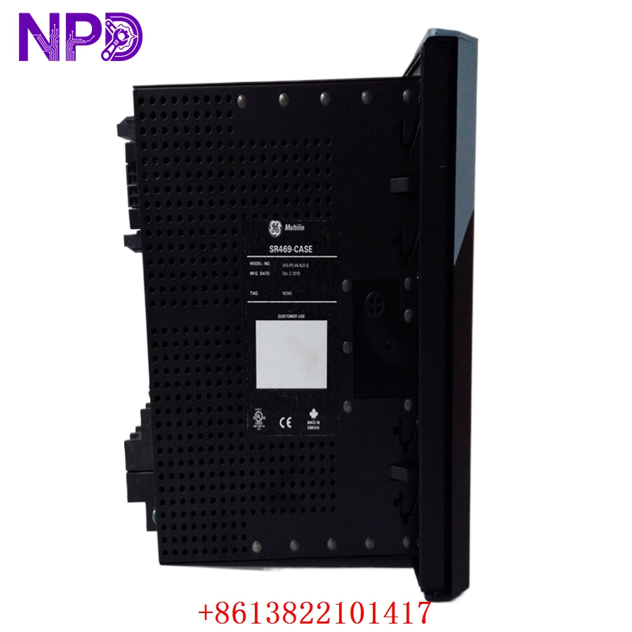
- Model: SR469-P5-HI-A20-E (SR469 / 469 Motor Management Series)
- Brand: General Electric (GE Multilin)
- Series: Multilin 469 Protection Relay Platform
- Core Function: Comprehensive Three-Phase Motor Management & Protection Relay
- Protection Elements: Delivers comprehensive motor protection tracking including thermal model overload protection, stator differential protection (87M), broken rotor bar detection, phase unbalance (46), voltage unbalance (47), underfrequency (81U), and locked rotor tracking.
- Metering Capabilities: High-accuracy real-time calculations tracking three-phase current, three-phase voltage, power factor (PF), active power (kW), reactive power (kVar), apparent power (kVA), and total energy usage (kWh).
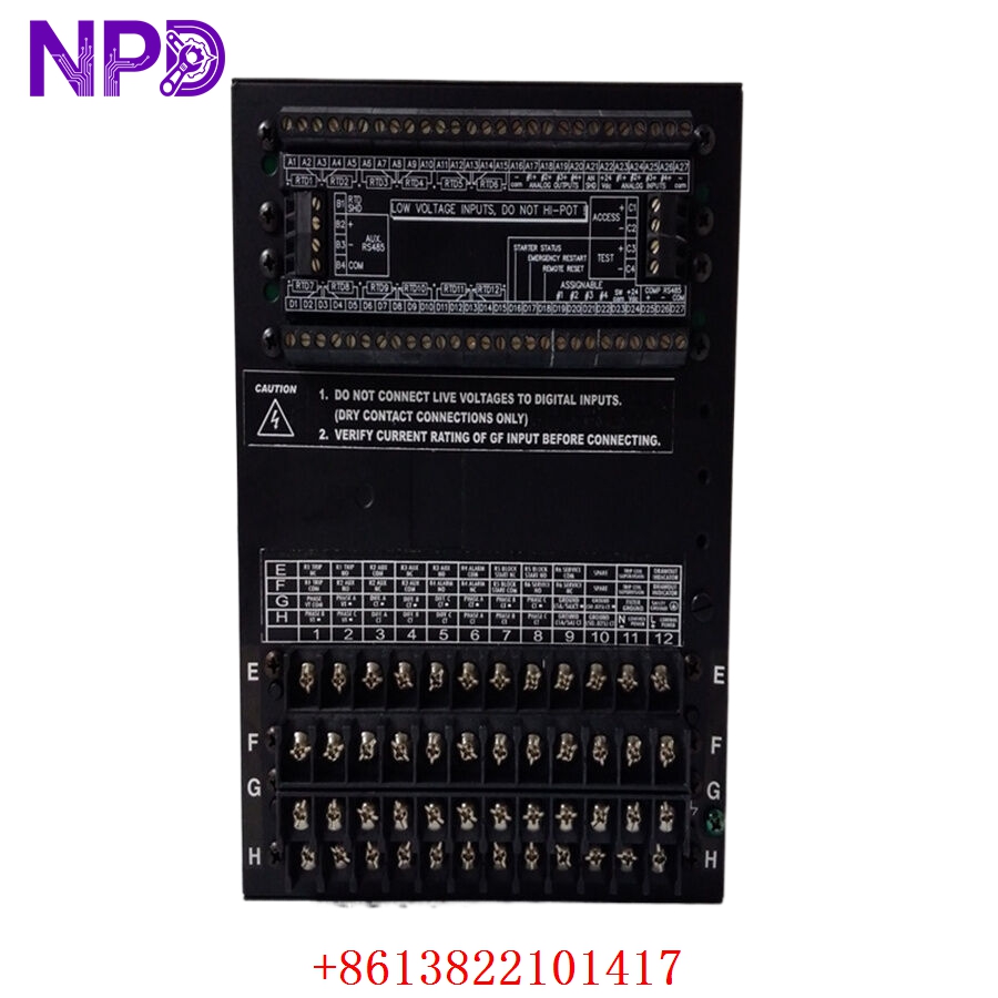
- Analog Interface (A20): Houses 4 fully programmable, isolated 4–20 mA analog output channels. These can be mapped to translate parameters like motor winding temperature, current load percentage, or line voltage directly to a DCS or PLC system.
- RTD Temperature Monitoring: Built-in inputs supporting up to 12 programmable Resistance Temperature Detectors (RTDs) directly embedded in the motor stator windings, bearings, and ambient casing.
- Waveform Capture & SOE: Integrated Sequence of Events (SOE) recorder capturing up to 40 events with 1 ms resolution, alongside configurable oscillography waveform data extraction for precise fault analysis.
- Drawout Hardware Enclosure: Formed as an integrated drawout unit. The relay chassis can be slid completely out of its switchgear housing for servicing or replacement without disturbing backplane wiring loops or shorting active CT wiring.
GE SR469-P5-HI-A20-E
GE SR469-P5-HI-A20-E
GE SR469-P5-HI-A20-E
Installation & Configuration Guide
Phase 1: Pre-Installation (Estimated Time: 20 minutes)
⚠️ Safety Critical Warning:
- The SR469-P5-HI-A20-E is a primary safety device protecting high-voltage motors (typically 2.3 kV to 13.8 kV). Before drawing out or swapping this device, ensure the circuit breaker is racked out to the “Test” or “Disconnected” position and tagged according to site Lockout/Tagout (LOTO) rules.
- Current Transformer (CT) Warning: The drawout case contains internal shorting bars for CT circuits. However, as an industry best-practice rule, always visually check that the external CT terminal isolation links are securely shorted before removing the relay chassis to eliminate dangerous high-voltage open-circuit hazards.
Required Toolkit:
- Grounded ESD (Electrostatic Discharge) wrist strap with verified ground link
- Flathead switchgear relay extraction tool
- Insulated terminal driver (Philips and Slotted combo)
- Calibrated protective relay test set (e.g., Doble or Omicron)
Phase 2: Removal (Estimated Time: 10 minutes)
- De-energize Control Power: Trip the specific control power breaker (90–300 VDC or 70–265 VAC) feeding the relay’s primary power input terminals.
- Release Drawout Latches: Open the front viewing door of the relay case. Push down on the dual mechanical release tabs located at the top and bottom corners of the chassis frame.
- Slide Out the Chassis: Pull the drawout handles firmly outward to disengage the backplane disconnect fingers. Slide the heavy inner chassis straight out of the fixed outer case.
- Isolate for Transport: Place the extracted relay assembly directly on a static-safe mat or within an ESD protective transport container.
Phase 3: Installation (Estimated Time: 15 minutes)
- Verify Backplane Pins: Inspect the inner copper contacts of the fixed outer case to make sure they are clear of dust, debris, or distortion.
- Match the Model Variant: Double-check the side tracking labels on the new replacement chassis to verify it reads exactly SR469-P5-HI-A20-E.
- Insert the New Chassis: Align the relay chassis rails with the inner tracks of the housing. Push the relay smoothly and firmly inward until the mechanical release latches snap securely back into the locked position.
- Tighten Safety Fasteners: If applicable, tighten the front faceplate thumb screws to ensure solid electrical grounding connectivity across the chassis frame.
Phase 4: Setting Transfer & Commissioning (Estimated Time: 40 minutes)
The Commissioning Protocol:
- Restore primary control power to the unit. The enhanced display screen should initialize immediately and pass through its system integrity diagnostics.
- Load Configuration Files: Connect an engineering laptop to the front-panel RS232 or USB diagnostic serial port. Open the EnerVista 469 Setup software tool and upload the verified motor setpoint file (.469 configuration matrix).
- Perform Secondary Injection Checks: Utilizing your relay test set, inject balanced three-phase currents into the test terminals. Cross-reference the values shown on the relay’s front display panel against your test set outputs to verify CT scaling and phase orientation.
- Un-short CT Links: Carefully restore the plant’s external CT shorting links back to their active, operational positions.
- Record the physical replacement timestamp, firmware version parameters, and technician verification markers inside the station protection asset logbook.
Frequently Asked Questions (FAQ)
Q1: Can an SR469-P5-HI-A20-E relay chassis slide into an older style SR469 case housing?
A: Yes. One of the primary advantages of the Multilin 469 platform is its mechanical backward compatibility. If your existing fixed outer case is wired for an older 5A CT configuration running high-voltage control power, the new SR469-P5-HI-A20-E chassis will slide directly into that existing case shell. This allows you to complete hardware maintenance upgrades without having to trace or re-terminate any of the backplane switchgear wiring.
Q2: What is the operational difference between the “LO” and “HI” power supply designations?
A: The power supply code dictates the allowable control voltage windows. The HI version on this module allows the relay to accept input power from 90 to 300 VDC or 70 to 265 VAC, which is standard across heavy industrial plants and utility substations using DC battery banks or station service transformers. A LO variant, by contrast, operates on low-voltage ranges (24–48 VDC or 20–48 VAC) and will be destroyed if wired into a high-voltage control bus.
Q3: Why is the “E” (Enhanced Display) variant chosen over standard screen configurations?
A: The E designation indicates an upgraded, high-contrast, vacuum fluorescent display (VFD) coupled with an optimized front faceplate layout. This layout provides clear visibility from wide viewing angles and under low-light or harsh switchgear room environments. It also provides more scannable, real-time scrolling diagnostic data during critical trip events or rapid troubleshooting sequences.