
Description
Product Parameters
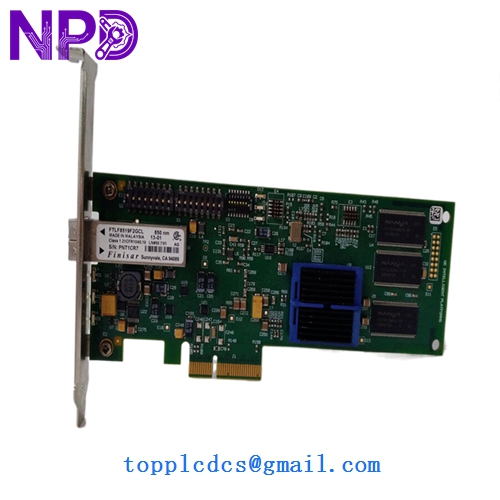
- Model Number: PCIE-5565-PIORC (PN: PCIE-5565PIORC-100000)
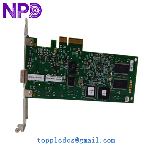
- Assembly Number: 350-9367875565-100000 A1
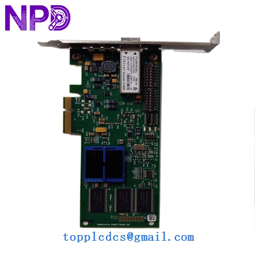
- Form Factor: Low-profile PCI Express (PCIe x1)
- Onboard Memory: 128 MB SDRAM
- Data Transfer Rate: 174 MB/s (sustained)
- Network Connection: Fiber optic (LC connectors, Multimode)
- Transmission Distance: Up to 300 meters (Multimode) / 10km (Singlemode)
- Operating Systems: Windows, Linux, VxWorks, Solaris
- Power Consumption: +3.3V DC at 2.0A (Typical)
- Country of Origin: USA
The PCIE-5565-PIORC is a high-speed, deterministic Reflective Memory (RFM) interface card designed for real-time data sharing between independent computers. It allows up to 256 nodes to share a common memory map over a fiber optic network, where any data written to one node’s memory is automatically and nearly instantaneously replicated in the memory of all other nodes. This “shared memory” architecture eliminates the overhead of traditional network protocols like TCP/IP, making it the industry standard for flight simulators, industrial test stands, and high-speed data acquisition systems requiring microsecond-level latency.
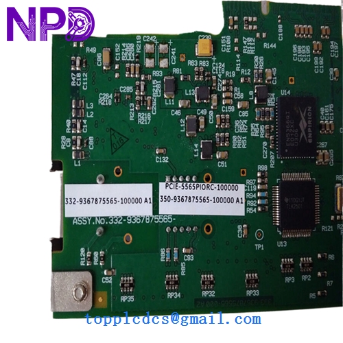
GE PCIE-5565-PIORC PCIE-5565PIORC-100000 350-9367875565-100000 A1
GE PCIE-5565-PIORC PCIE-5565PIORC-100000 350-9367875565-100000 A1
GE PCIE-5565-PIORC PCIE-5565PIORC-100000 350-9367875565-100000 A1
Model Comparison
The PCIE-5565-PIORC is the PCI Express version of the Reflective Memory series, replacing the older PCI-5565 (standard PCI) and PMC-5565 (mezzanine) cards. While the PCIE-5565RC variant typically features a standard-height bracket, the PIORC designation often refers to specialized configurations including low-profile brackets or specific fiber-optic transceiver types (Multimode vs. Singlemode). Compared to newer 5565PIORC-2xxxxx models, the 100000 suffix denotes the standard 128MB memory configuration; higher suffixes often indicate expanded memory or specialized environmental ruggedization for aerospace applications.
Operation Tips
- Network Topology: Reflective Memory operates in a physical ring or a star configuration (using a hub). Ensure the “TX” (Transmit) of one node connects to the “RX” (Receive) of the next to complete the loop.
- Interrupt Management: Use the onboard interrupt registers to notify the local CPU only when critical data is received, preventing the processor from being overwhelmed by non-essential memory updates.
- Fiber Handling: Fiber optic LC connectors are sensitive to dust. Keep the protective caps on until the moment of installation and use a dedicated fiber cleaner if signal loss is detected in the diagnostics.
- Status Monitoring: Monitor the “Link” and “Signal” LEDs on the card bracket; a flickering or dark Link LED typically indicates a break in the fiber loop or a faulty transceiver on an upstream node.