
Description
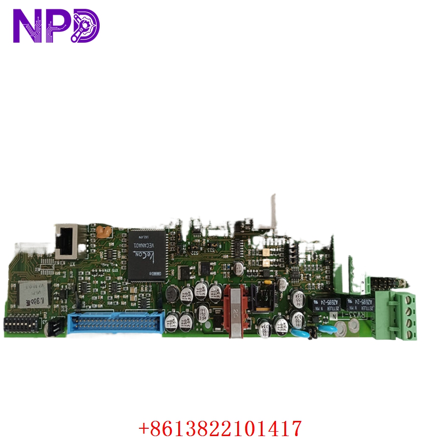
The GE RV33-1 is a precision rotary variable resistor, commonly used as a potentiometer or position sensor in industrial control feedback loops. It provides a variable resistance output proportional to the angular position of its shaft. This component is essential in systems where precise mechanical orientation needs to be converted into an electrical signal for monitoring or control purposes.
Technical Specifications
| Parameter | Detail |
| Model | RV33-1 |
| Manufacturer | General Electric (GE) |
| Device Type | Rotary Potentiometer / Variable Resistor |
| Function | Position Feedback / Reference Setting |
| Mounting | Panel mount (bushing mount) |
| Rotation | Single-turn (standard) |
| Construction | Industrial-grade resistive element |
Fields of Application
The RV33-1 is widely used in legacy and modern industrial applications for manual adjustment or position monitoring:
- Process Control: Manual setpoint adjustment for motor speed or temperature loops.
- Instrumentation: Precision calibration and zero-adjustment in measurement devices.
- Mechanical Linkage: Feedback for valve positions, damper angles, or conveyor alignment.
- Test Equipment: Variable signal generation for laboratory testing.
Product Introduction
The RV33-1 functions by using a conductive element—typically a resistive wire or carbon film—that is traversed by a wiper attached to the rotating shaft. As the shaft turns, the electrical path length between the wiper and the end terminals changes, resulting in a change in resistance. In many industrial control circuits, this variable resistance is used to create a variable voltage divider, which provides a signal to a PLC analog input card that represents the physical position of the device.
Product Use Instructions
- Mounting: Insert the threaded bushing through the designated panel hole and secure it with the provided nut and lock washer.
- Wiring:
- Terminal 1 (End): Connect to the reference voltage (e.g., +10V or +5V).
- Terminal 2 (Wiper): Connect to the signal input of your controller (e.g., PLC Analog Input).
- Terminal 3 (End): Connect to the common or ground (GND) return.
- Calibration: After physical installation, rotate the shaft to its minimum and maximum positions to calibrate the software scaling within your control system.
- Integration: Ensure the mechanical linkage to the shaft is free of excessive lateral play, as this can introduce signal “noise” or jitter.
Product Use Precautions
The RV33-1 is a mechanical device subject to wear; ensure it is protected from excessive vibration, moisture, and conductive dust, which can cause intermittent contact (resistance spikes). Do not exceed the maximum power dissipation (wattage) rating of the unit, as this will burn out the resistive element. Avoid forcing the shaft beyond its rotational limit, as this will damage the internal mechanical stops.
Frequently Asked Questions (Q&A)
Q: My output signal is flickering; what is the cause?
A: This is likely caused by oxidation on the resistive element or dirt/dust inside the casing. You may try cleaning it with an electronics-grade contact cleaner, but if wear is advanced, the unit should be replaced.
Q: Can I use this for high-current motor control?
A: No. This is a low-power signal device. It is intended for feedback or reference inputs; using it to directly control motor current will cause immediate destruction of the component.
Q: How do I know if the RV33-1 is linear or logarithmic?
A: Standard industrial models like the RV33-1 are typically “linear,” meaning resistance changes in direct proportion to the shaft angle. You can verify this by measuring the resistance between the wiper and an end terminal while rotating the shaft at regular intervals.
Product Operation Methods
The device operates on the principle of a potential divider. When supplied with a constant reference voltage, the output voltage at the wiper terminal corresponds directly to the wiper’s mechanical position. It operates as a passive device, requiring no power other than the reference voltage it receives from the control loop. Maintenance is minimal, primarily involving periodic checks for electrical continuity and mechanical tightness of the shaft linkage.