
Description
✨ Product Overview
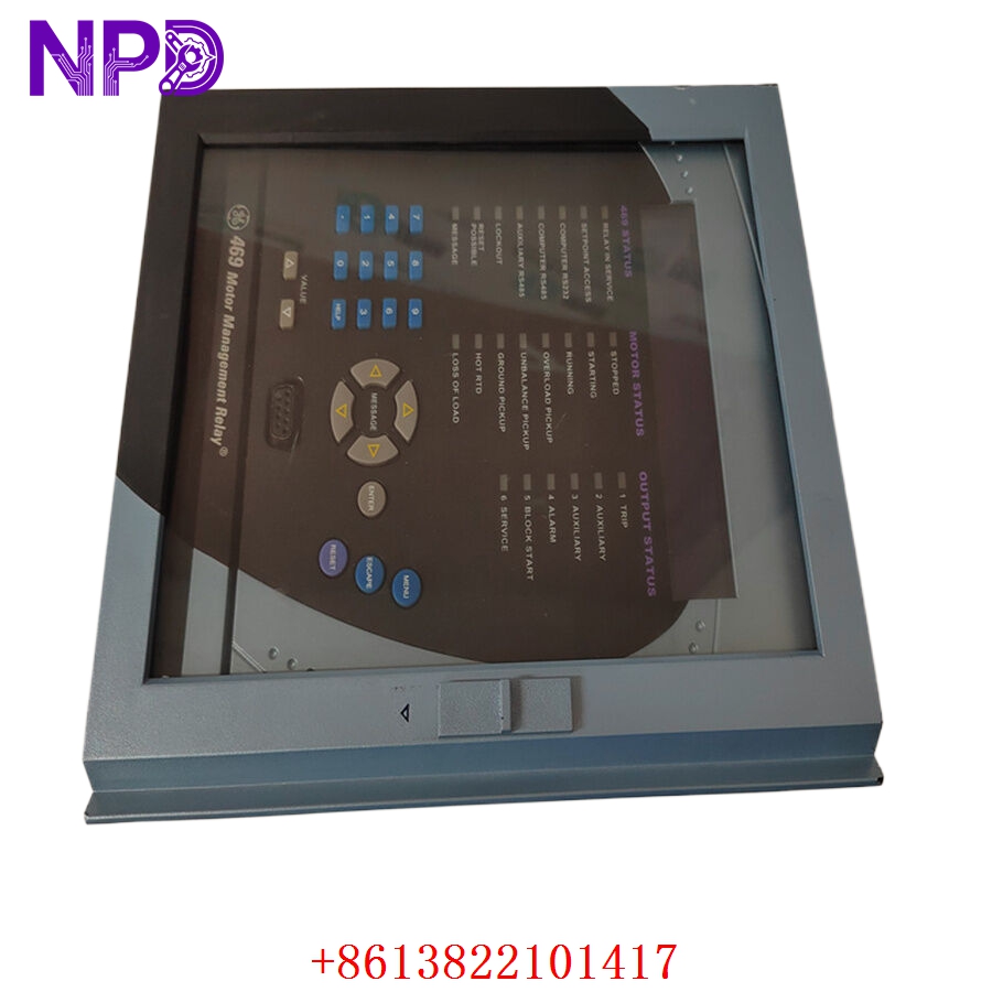
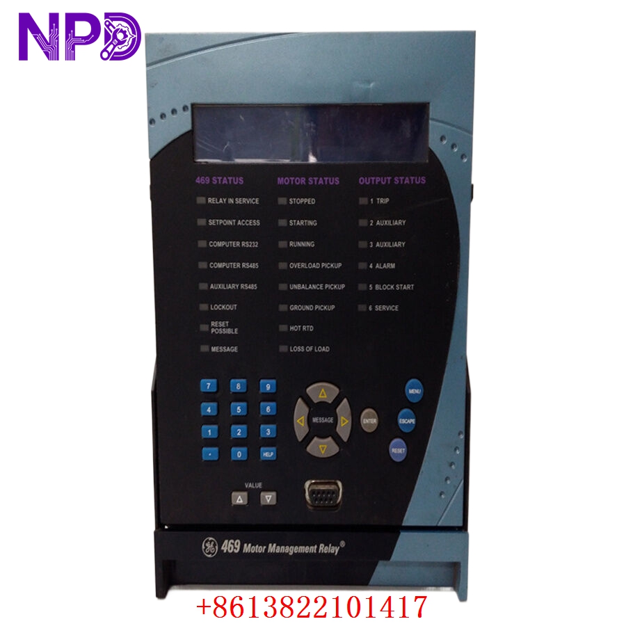
The GE Multilin SR469-P5-HI-A20-E is an advanced, microprocessor-based motor management relay designed to provide comprehensive protection, control, and monitoring for medium to large horsepower three-phase induction and synchronous motors. Part of the renowned SR469 series, this unit integrates thermal overload protection, extensive current, voltage, and RTD-based monitoring to safeguard critical machinery from catastrophic failures while maximizing plant operational runtime.
📋 Product Datasheet & Parameters
| Parameter | Specification |
| Target Model | GE SR469-P5-HI-A20-E |
| Brand Manufacturer | General Electric (GE Multilin) |
| Product Type | Motor Management Protection Relay |
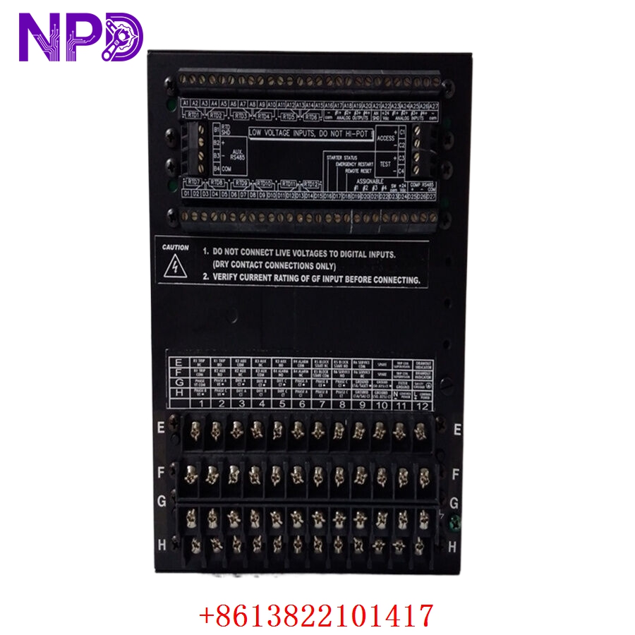
| Current Inputs | 5A Phase CT secondary inputs |
| Power Supply (HI) | 125–250V DC / 90–300V AC (High Range Voltage Input) |
| Analog Outputs (A20) | Four 4-20mA current outputs (Configurable) |
| Display Option (E) | Enhanced display front panel with localized diagnostics |
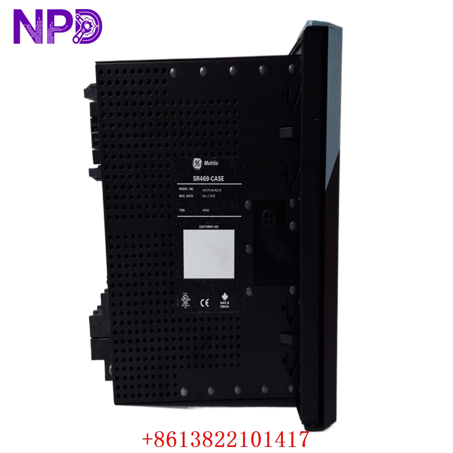
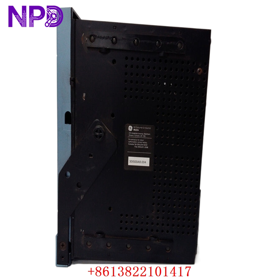
| Dimensions | 8.8″ W x 6.9″ H x 9.5″ D (Standard drawout design case) |
| Weight | Approx. 3.85 kg |
| Country of Origin | Canada / USA |
🏭 Application Fields
- Heavy Duty Pump Stations: Comprehensive protection for large water utility and pipeline transport pumps.
- Compressor Systems: Thermal monitoring and protection loops for vital industrial air and gas compressors.
- Mining & Metal Mills: Manages structural stress and load jam detection on high-torque rock crushers and conveyor drives.
- Refineries & Chemical Plants: Safeguards explosion-proof motors driving hazardous process loops and fans.
GE SR469-P5-HI-A20-E-H
GE SR469-P5-HI-A20-E-H
GE SR469-P5-HI-A20-E-H
⚙️ Product Usage Instructions
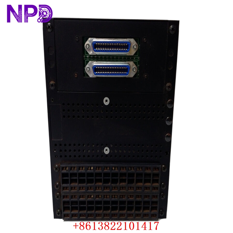
- Chassis Extraction Safety: Ensure external current transformer (CT) shorting links are engaged before drawing out the relay inner chassis to prevent dangerous open-circuit voltages.
- Power Connection Termination: Confirm your supply source matches the High Voltage (HI) range input parameters (125-250V DC or 90-300V AC) before energizing the control terminals.
- Sensor Wiring Configuration: Route the 12 assignable RTD inputs using shielded twisted-pair cables, grounding the shields at the relay terminal block only to prevent ground loop noise.
- Parameter Programming: Connect via the front RS232 port or rear Modbus interface using EnerVista SR469 Setup software to upload customized motor thermal damage curves and tripping thresholds.
❓ Q&A: Frequently Asked Questions
Q1: What does the “P5” designated code mean in this model configuration?
💡 A: The “P5” parameter indicates that the relay is equipped with standard 5A Phase CT secondary inputs. Ensure your field-installed current transformers match this rating for accurate current metering.
Q2: How does the relay protect the motor against sudden rotor locking?
💡 A: The SR469 features dedicated mechanical jam and stalled rotor detection logic, monitoring high-current magnitudes combined with speed switch inputs to isolate power before thermal damage occurs.
Q3: Can I replace older SR469 units without rewiring the entire cabinet panel?
💡 A: Yes, the drawout case structure allows the inner relay module to be easily pulled out and swapped with a compatible model version, leaving the outer wire terminal chassis fully intact.