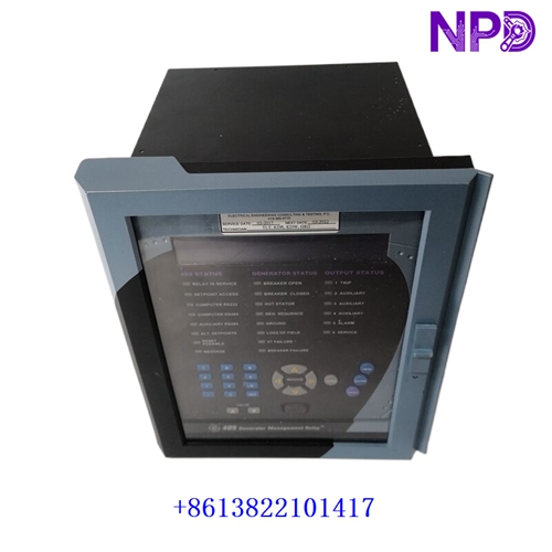
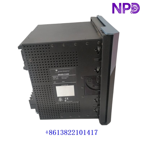
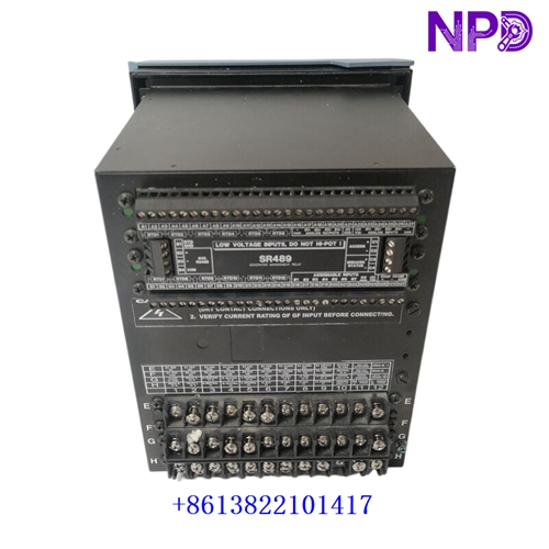

Description
Product Specifications & Datasheet
- Brand: GE (General Electric / Multilin)
- Model: SR489-P5-HI-A20-E
- Series: 489 Motor Management Relay Series
- Product Name: Digital Feeder / Motor Protection Relay
- Place of Origin: United States / Canada
- Lifecycle Status: Mature / Industrial Power Protection Spare Part
- Dimensions: Standard 19-inch Rack / Panel-Mount Case (approx. 177 mm x 216 mm x 241 mm)
- Weight: 3.60 kg
- Origin Country: USA / Canada
- Power Rating: High Control Power Supply (90-300V DC or 70-265V AC, 48-62 Hz)
Operating Procedures & Usage Guidelines
- Pre-Installation Check: Ensure all associated motor feeder breakers are opened, locked out, and tagged out before wiring or installing the relay.
- Panel Mounting: Secure the relay firmly into the cutout of the switchgear control compartment using the designated mounting brackets and hardware.
- Wiring & Termination: Connect current transformers (CTs), voltage transformers (VTs), control power, and trip/alarm output contacts strictly according to the terminal diagram on the unit casing.
- Configuration & Startup: Energize control power and use the front keypad or EnerVista 489 Setup software via the front USB/serial port to input motor nameplate data and protection settings.
Emergency Shutdown Operation
- Manual Trip Initiation: Press the front-panel emergency trip or breaker open key if an immediate manual shutdown of the protected motor is required.
- Hardware Trip Contact: Trigger the internal high-speed trip output contacts to command the main breaker to drop out instantly during critical plant emergencies.
Troubleshooting & Common Issues
- Relay Not Powering On: Check the incoming control power supply voltage at the designated terminals to ensure it falls within the 90-300V DC or 70-265V AC range.
- CT / VT Mismatch Alarms: Verify that the primary and secondary transformer ratios entered in the relay settings match the physical instrument transformers installed in the switchgear.
- Communication Link Failure: Check the RS485 or Ethernet communication cable wiring, polarity, and baud rate settings when connecting to a DCS or SCADA system.
Routine Maintenance & Care
- Battery Check: Periodically inspect and test the internal real-time clock battery to ensure event logs and time stamps are preserved during power outages.
- Terminal Tightening: Check all screw terminals and plug-in connectors periodically to prevent loosening caused by heavy industrial switchgear vibration.
- Event Log Review: Routinely download and review event records, fault reports, and oscillography data via the software interface to analyze motor starting trends and past trips.
Frequently Asked Questions (Q&A)
- Q: What is the primary function of the GE SR489-P5-HI-A20-E relay?
- A: It provides comprehensive management, metering, and protection for medium-to-large AC motors, guarding against thermal overload, short circuits, and phase unbalance.
- Q: What software is used to program and monitor this relay?
- A: GE EnerVista 489 Setup software is used for configuration, setting management, and retrieving oscillography waveforms.
- Q: What does the ‘HI’ designation mean in the catalog number?
- A: It designates the High range control power supply option, accommodating wide AC/DC auxiliary voltage inputs.