Description
Product Overview
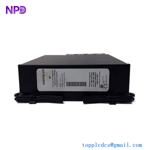
The GENERAL ELECTRIC 151X1235BC01SA01 is a GE industrial Ethernet switch assembly designed for use within GE industrial control and turbine-control networking architectures. It is identified as a 10-slot Ethernet Switch and is associated with the GE 151X boards and modules family.
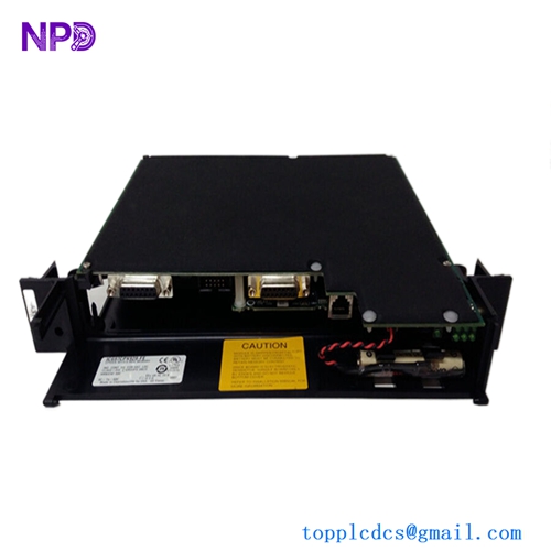
The unit provides 10 Ethernet ports and an additional USB port. Its backplane-based mounting arrangement allows it to be installed as part of the associated control-system hardware rather than being used as a typical standalone office Ethernet switch. The assembly uses a vented metal sub-chassis and front faceplate for industrial cabinet installation.
In GE control applications, the switch is used to provide network connectivity between controllers and other system components. Some product references also identify the assembly as a UCSB/CSLA copper module, making the complete part-number and system configuration important when selecting a replacement.
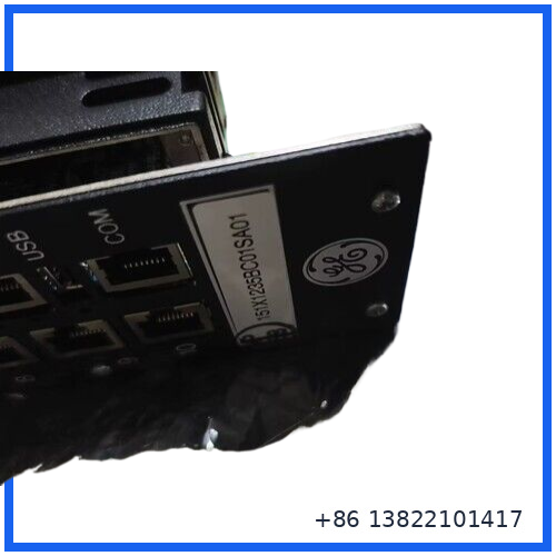
Main Features
- GE industrial Ethernet switch assembly
- 10 Ethernet ports
- 1 USB port
- Backplane-based mounting
- Vented metal chassis
- Front access to communication ports
- Screw-secured faceplate
- Designed for GE industrial control system applications
- Suitable for replacement and spare-parts inventory
- Exact system compatibility should be checked against the existing hardware configuration
Technical Specifications
| Parameter | Specification |
|---|---|
| Brand | GENERAL ELECTRIC |
| Model | 151X1235BC01SA01 |
| Product Type | 10-Slot Ethernet Switch |
| Ethernet Ports | 10 |
| USB Port | 1 |
| Mounting | Backplane-based |
| Faceplate | Metal |
| Chassis | Vented metal sub-chassis |
| Series | 151X Boards and Modules |
| Grouping | Group 1 |
| Application | GE industrial control / turbine-control networking |
| Communication Type | Ethernet |
| Indicators | No dedicated LED indicators reported |
| Country of Origin | USA is commonly listed |
| Exact power/network ratings | Verify from unit nameplate and system documentation |
The published information for this part is not completely consistent between secondary sources. For this reason, items such as input voltage, Ethernet signaling details, environmental limits, and exact internal board configuration should be confirmed from the physical unit or GE system documentation before installation.
Operating Function
The primary job of the switch is to provide Ethernet communication paths within the control-system network.
A typical communication path can be understood as:
Controller → Ethernet Switch → Control Network Devices
The switch allows multiple Ethernet-connected devices to share the same industrial network infrastructure. In a GE control cabinet, this can simplify the physical network arrangement and provide communication paths between control hardware and associated system equipment.
The UCSB/CSLA terminology found with this part number is important because it indicates that the assembly may form part of a specific GE control architecture rather than functioning as a generic commercial Ethernet switch.
Installation & Replacement Guide
Before replacing the existing unit:
- Record the complete part number, including every suffix.
- Photograph the existing wiring and Ethernet connections.
- Label each Ethernet cable before removal.
- Confirm the replacement has the same connector arrangement.
- Check the mounting points and backplane interface.
- Disconnect power according to the equipment manufacturer’s procedure.
- Remove the existing assembly carefully to avoid stressing the backplane connectors.
- Install the replacement unit and secure the faceplate.
- Reconnect Ethernet cables according to the original port arrangement.
- Restore system power and check network communication.
Important Compatibility Check
Do not select a replacement based only on the description “10-slot Ethernet switch.” The complete part number 151X1235BC01SA01 should be matched because GE control-system hardware can have similar-looking assemblies with different functions or revisions.
Inspection Before Installation
For a replacement or surplus unit, check:
- Part number and revision markings
- GE identification label
- Ethernet connector condition
- USB connector condition
- Backplane connector pins
- Mounting hardware
- Chassis deformation
- Corrosion or contamination
- Signs of overheating
- PCB damage visible through the enclosure
- Any missing screws or mechanical parts
For long-term spare inventory, keep the unit in an ESD-safe package and store it in a clean, dry environment.
Troubleshooting
No network communication
Check the Ethernet cables first, then verify that the cables are connected to the correct ports. Confirm that the replacement part number exactly matches the original assembly.
Communication works intermittently
Inspect connectors and cables for loose connections. Also check the backplane interface and cabinet grounding conditions.
System does not recognize the replacement
A visually similar GE Ethernet assembly may not be electrically or functionally interchangeable. Confirm the complete part number, revision, system configuration, and associated control-system documentation.
Physical installation problem
Check the backplane alignment and mounting standoffs. Do not force the assembly into position because connector damage can result.
Typical Applications
The 151X1235BC01SA01 can be used in applications involving:
- GE industrial control systems
- Turbine control equipment
- Generator control systems
- Industrial Ethernet networks
- Control cabinet networking
- Legacy GE automation systems
- Replacement and maintenance of GE control hardware
Maintenance Recommendations
Industrial Ethernet hardware is usually more reliable when the surrounding cabinet environment is controlled.
Recommended maintenance includes:
- Keep cabinet ventilation paths clean.
- Check Ethernet connectors during scheduled shutdowns.
- Inspect cables for mechanical damage.
- Check for excessive dust or contamination.
- Record communication-related alarms.
- Keep a verified spare available for critical systems.
- Record the complete part number and revision of every installed unit.
FAQ
Q: What is the main function of 151X1235BC01SA01?
A: It is a GE 10-port Ethernet switch assembly used to provide Ethernet communication within compatible industrial control architectures.
Q: How many Ethernet ports does it have?
A: Published technical information identifies 10 Ethernet ports, plus one USB port.
Q: Is it a normal commercial Ethernet switch?
A: No. It is an industrial control-system assembly associated with GE’s 151X hardware family and should be matched to the intended GE control architecture.
Q: Can I replace another GE 10-port switch with this model?
A: Not automatically. The complete part number, connector arrangement, system configuration, and revision should be checked before replacement.
Q: What should I verify before ordering?
A: Verify the complete model number 151X1235BC01SA01, physical connectors, mounting arrangement, and the control-system application.
Related GE Models
For GE industrial control spare-parts sourcing, related hardware may include:
- 151X1235BC01SA01 – 10-Slot Ethernet Switch
- 151X1235DB15SA01 – EX2100e PCM Controller
- DS200DTBBG1ABB – GE Mark V Control Board
- DS200TCCAF1BDF – GE Mark V Control Board
- DS200SDCIG2AFB – GE Mark V Control Board
- IS200ISBBG1AAB – GE Control Board
- IS200CABPG1BAA – GE Control Board
- DS200BDAAG1AAA – GE Control Board
- IS200DSFCG1AEB – GE Control Board
- IS200DRLYH1BBB – GE Relay/Control Board
Product Summary
The GENERAL ELECTRIC 151X1235BC01SA01 is a specialized 10-port Ethernet Switch for GE industrial control-system applications. Its backplane mounting, 10 Ethernet interfaces, USB port, and industrial metal enclosure make it different from a conventional standalone Ethernet switch.
For replacement work, the most important point is complete part-number matching. Before installation, compare the existing unit, connectors, mounting arrangement, revision information, and system documentation to ensure the replacement is appropriate for the target GE control system.