Description
Product Overview
The GE DS200DCFBG1BNC is a DC Power Supply and Feedback Board for the GE Mark V industrial control platform. The board is identified by the DCFB functional acronym and is used in GE drive and turbine-control related equipment.
The DCFB board provides control-level power and cabinet fan power while also handling several monitoring and feedback functions. Depending on the host application, it can interface with motor voltage, armature current and voltage, field current, and AC line signals.
The complete identification DS200DCFBG1BNC is important. GE’s board-numbering system uses the suffix to identify functional and artwork revisions, and the manufacturer’s documentation specifically emphasizes that all digits should be considered when ordering a replacement.
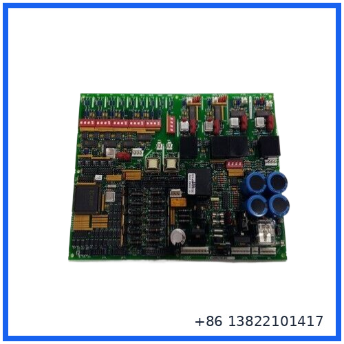
🔧 Main Features
- GE General Electric industrial control board
- Mark V / DS200 series
- DCFB DC power supply and feedback function
- Model: DS200DCFBG1BNC
- Base board: DS200DCFBG1B
- Provides control-level power
- Provides enclosure/cabinet fan power
- Motor voltage feedback/attenuation circuitry
- AC and DC monitoring circuits
- Motor field power circuitry
- SCR gate-driver related circuitry
- On-board fuse protection
- LED/neon fuse-status indication
- Multiple test points
- Configurable jumpers and DIP switches
- Designed for legacy GE drive and control equipment
📋 Product Datasheet
| Parameter | Specification |
|---|---|
| Brand | General Electric |
| Model | DS200DCFBG1BNC |
| Base Model | DS200DCFBG1B |
| Series | Mark V DS200 |
| Functional Acronym | DCFB |
| Product Type | DC Power Supply / Feedback Board |
| Main Function | Control-level power, fan power and signal feedback |
| Input Power | 38–115 VAC range reported for the DCFB application |
| Control-Level Outputs | +5 VDC, +15 VDC and +24 VDC supply circuits |
| Monitoring | AC/DC and motor feedback signals |
| Fuses | 3 onboard protected fuses |
| Test Points | 5 voltage/signal test points |
| Configurable Hardware | Jumpers and DIP switches |
| Communication | Analog feedback/interface with associated control boards |
| Related Control Boards | SDCC / LDCC depending on application |
| Instruction Manual | GEI-100028 / GEI-100028C |
| Application | GE Mark V drives and industrial control |
| Weight | Approx. 2 lb reported for this revision |
| Condition | New Surplus, subject to actual inventory |
The DCFB board’s input and output circuits are application-dependent. The published DCFB documentation identifies 38–115 VAC input power and control-level power supply circuits; exact terminal usage should be verified against the installed drive configuration.
⚡ DC Power Supply Function
The primary job of the DCFB board is to generate and distribute control-level power within the associated drive system.
The board includes circuits associated with:
- Control-level power supplies
- Motor field power
- SCR gate pulse-driver circuits
- AC line monitoring
- DC motor signal monitoring
- Motor voltage feedback
- Motor current/voltage feedback
- Cabinet fan power
This makes the board more than a conventional power supply. It combines power conversion with feedback and monitoring functions required by the associated GE drive/control architecture.
🔌 Feedback & Monitoring
The DCFB board provides an analog representation of motor voltage to associated control boards such as SDCC or LDCC. Its circuitry can also be associated with monitoring of armature voltage/current, field current, AC line current and AC line voltage.
This feedback function is important when troubleshooting a Mark V drive. A board can appear to have a power-supply problem when the actual issue is related to an incorrect feedback signal, field circuit, wiring, fuse, or downstream component.
🛡️ Fuse & Diagnostic Circuitry
The board includes three protected fuses. Diagnostic components on the PCB provide visual indication of fuse-related conditions.
Available technical documentation identifies:
- FU1
- FU2
- FU3
- CR51 red LED
- CR55 red LED
- LT1 neon indicator
Five test points are also provided for checking regulated supply and feedback-related signals.
🎛️ Jumpers & DIP Switches
The DCFB board contains configurable hardware used to adapt the board to the particular drive application.
The commonly documented configuration includes:
- Multiple configurable jumpers
- Seven DIP switches
- Voltage-feedback scaling selections
- Application-specific configuration settings
Do not copy jumper or DIP-switch settings from a different revision. Before removing the original board, photograph every jumper and switch position and compare the complete board number.
🏭 Typical Applications
The DS200DCFBG1B family is associated with GE industrial drive and control equipment including:
- DC2000
- AC2000
- CB2000
- FC2000
- ME2000
- EX2000
- GF2000
- GE Mark V drive systems
- Industrial motor-control equipment
- Legacy turbine/drive control installations
The EX2000 application can use the DCFB board differently from some drive applications, so the host equipment should always be confirmed before installation.
🛠️ Installation & Replacement Guide
Before replacing the board:
- Shut down the associated equipment according to the plant procedure.
- Isolate all applicable electrical power sources.
- Record the complete board part number and revision.
- Photograph all connectors, jumpers and DIP-switch positions.
- Label cables before removal.
- Inspect the replacement board for shipping damage.
- Confirm the replacement has the required suffix.
- Transfer configuration settings only after verifying revision compatibility.
- Reconnect every cable to the corresponding connector.
- Check fuse and connector conditions.
- Restore power according to the approved commissioning procedure.
- Verify control-level voltage and feedback signals.
- Check the associated SDCC/LDCC or other control board for proper communication and status.
- Test the drive under controlled operating conditions.
The DCFB documentation specifically stresses correct connector reconnection and matching board configuration during replacement.
🔄 Compatibility & Revision Notes
The DS200DCFBG1BNC belongs to the DS200DCFBG1B family. Related suffixes can include versions such as:
- DS200DCFBG1BLC
- DS200DCFBG1BNC
- DS200DCFBG1BPC
- DS200DCFBG1BKC
- DS200DCFBG1BDB
- DS200DCFBG1BGB
- DS200DCFBG1BJB
These suffixes should not automatically be treated as interchangeable. GE’s identification system distinguishes functional and artwork revisions, and the exact revision can affect compatibility.
❓ Frequently Asked Questions
Q1: What is the DS200DCFBG1BNC?
A: It is a GE Mark V DCFB DC Power Supply and Feedback Board.
Q2: What does DCFB stand for?
A: DCFB is the functional acronym used for this GE DC power supply/feedback board.
Q3: What is the main function of the board?
A: It provides control-level power and fan power while also handling motor and AC/DC feedback and monitoring functions.
Q4: Is this an analog I/O card?
A: No. It is primarily a power supply and feedback board with integrated monitoring circuits.
Q5: What equipment uses the DCFB board?
A: The family is used across several GE drive/control platforms, including AC2000, DC2000, FC2000, ME2000, CB2000 and EX2000 applications.
Q6: Can DS200DCFBG1B replace DS200DCFBG1BNC?
A: Not automatically. DS200DCFBG1B is the base identification, while the additional suffix identifies a particular revision/configuration. Match the complete installed part number whenever possible.
Q7: Does the board contain adjustable settings?
A: Yes. DCFB boards use configurable jumpers and DIP switches for application-specific settings.
Q8: What should be checked before replacement?
A: Check the complete part number, revision, jumper settings, DIP switches, connector positions, host drive model and original system documentation.
📦 Recommended GE Related Models
- DS200DCFBG1BNC – DCFB Power Supply/Feedback Board
- DS200DCFBG1B – DCFB Power Supply Board
- DS200DCFBG1BLC – DCFB Power Supply Board
- DS200DCFBG1BPC – DCFB Power Supply Board
- DS200DCFBG1BKC – DCFB Power Supply Board
- DS200DCFBG1BDB – DCFB Power Supply Board
- DS200DCFBG1BGB – DCFB Power Supply Board
- DS200DCFBG1BJB – DCFB Power Supply Board
- DS200LDCCG1A – Mark V Drive Control Board
- DS200SDCCG1A – Mark V Drive Control Board
These are related GE Mark V components and should not be considered direct substitutes without checking the original system configuration.
🔍 Inspection Before Shipment
For an industrial spare board, recommended inspection includes:
- Verify complete DS200DCFBG1BNC identification
- Check board revision markings
- Inspect PCB for corrosion or physical damage
- Check all connectors and pins
- Inspect fuse holders and fuses
- Check jumper positions
- Check DIP-switch condition
- Inspect LEDs and indicator components
- Confirm mounting hardware
- Use ESD-safe packaging
- Perform functional testing when suitable test equipment is available
Procurement Tip: When requesting this board, provide the complete marking DS200DCFBG1BNC, rather than only “DS200DCFBG1B.” The suffix is significant for replacement compatibility.