
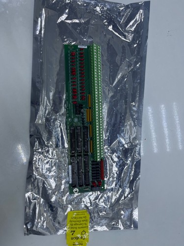
Description
The GE DS200TBQCG1ABB is a specialized Analog Input Termination Board designed for the Speedtronic Mark V Gas Turbine Control System. It serves as the primary interface for field-wired analog signals, converting external sensor data into a format compatible with the control processors. This board is engineered to handle various analog signal types, including 4-20mA current loops and voltage inputs, ensuring high-speed data acquisition for critical turbine monitoring.
- System Compatibility: GE Speedtronic Mark V Control
- Signal Inputs: Supports up to 15 analog input channels
- Termination Type: Two terminal blocks with 36 silver-plated screw terminals each
- Communication: Interconnects with the STCA or TCDA boards via ribbon cables
- Circuit Protection: Integrated onboard jumpers for hardware configuration and signal scaling
- Operating Voltage: 24V DC nominal for loop-powered transmitters
Product Datasheet
| Feature | Specification |
|---|---|
| Model | GE DS200TBQCG1ABB |
| Series | Mark V Speedtronic |
| Dimensions | 280 x 125 x 40 mm |
| Weight | 0.65 kg |
| Country of Origin | USA |
| Input Channels | 15 Differential or Single-ended |
| Mounting | DIN-rail or standoff mounting in <R>, <S>, or <T> cores |
Application Fields
This termination board is critical for the automation and monitoring of heavy-duty gas and steam turbines, specifically in:
- Power Generation Plants: Interfacing pressure, temperature, and flow transmitters with the Mark V controller.
- Oil & Gas Industry: Used in mechanical drive applications for centrifugal compressors.
- Turbine Safety Systems: Providing feedback for vibration monitoring and fuel valve positioning.
- Industrial Automation: Real-time data logging for legacy industrial control upgrades.
Product Instructions
- Preparation: Verify that the turbine is in a safe state and the Mark V control panel power is isolated if necessary for the specific core.
- Wiring: Connect field sensor wiring to the screw terminals. Ensure proper polarity for 4-20mA loops to avoid signal loss.
- Jumper Configuration: Set the onboard Berg jumpers (JP1, JP2, etc.) to match the specific input type (Voltage vs. Current) as defined in the GE Mark V application manual.
- Cabling: Attach the 2R, 2S, or 2T ribbon cables to the designated headers on the DS200TBQCG1ABB to link the inputs to the I/O processor.
- Verification: Power the system and use the Mark V “LCC” or diagnostic software to verify that the analog values are scaling correctly at the HMI.
Q&A – Common Questions
Q1: What is the significance of the “ABB” suffix in the part number? A1: The suffix denotes the specific revision history and hardware version. “ABB” indicates a specific version of the board layout and component selection that must be matched or exceeded for system compatibility.
Q2: Can I replace a DS200TBQCG1A with a DS200TBQCG1ABB? A2: Generally, yes. In the Mark V system, later revisions (like ABB) are usually backward compatible with earlier versions (like A), but always verify jumper settings as they may differ between revisions.
Q3: How do I troubleshoot a “Signal Open” fault on this board? A3: Check the integrity of the field wiring at the screw terminals, ensure the loop power fuse (if external) is intact, and verify the ribbon cable connection to the I/O processor board is secure.
Related Product Recommendations
- GE DS200TCDAG1B | Mark V Digital I/O Board
- GE DS200TCQCG1A | Mark V Analog Configuration Board
- GE DS200STCAG1A | Mark V Signal Terminal Card
- GE DS200SDCCG1A | Mark V Drive Control Card
- GE DS200TCPAG1A | Mark V Power Distribution Board