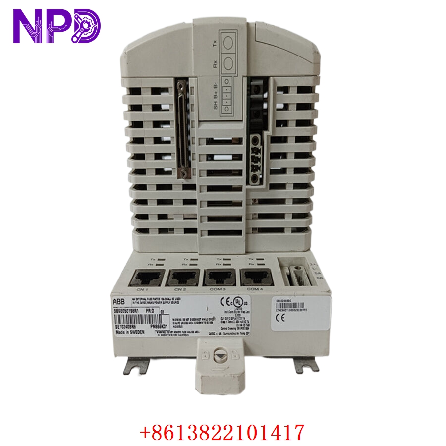

Description
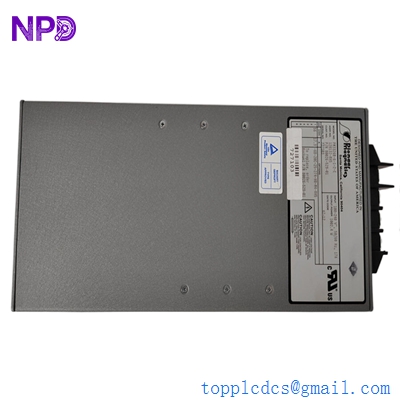
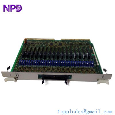
The GE DS68200SRB1C1B is a high-reliability engine control module designed for heavy-duty industrial applications. As part of General Electric’s control product line, this module (often categorized within the Speedtronic or Mark series architecture) is engineered to provide precise monitoring and regulation of engine parameters, including fuel delivery, speed governing, and protection sequencing in power generation and mechanical drive environments.
⚙️ Technical Specifications
- Dimensions: 320 mm x 280 mm x 100 mm
- Weight: 2.5 kg
- Country of Origin: United States
- Power Input: 24V DC / 125V DC (Configurable)
- Operating Temperature: -20°C to +70°C
- Protection Class: IP54 (Enclosed mounting required)
🏗️ Application Areas
- Gas and Diesel Engine Management
- Industrial Power Generation Plants
- Oil & Gas Compressor Drives
- Distributed Energy Resources (DER)
- Marine Propulsion Control Systems

📖 Product Usage Instructions
Install the control unit within a vibration-dampened, climate-controlled cabinet. Ensure all connections to engine sensors (speed pickups, thermocouples, pressure transmitters) are routed through dedicated shielded cable trays to eliminate electromagnetic interference. The module relies on precise feedback loops; therefore, the wiring to the terminal blocks must be checked for continuity and tightness prior to initial activation.
🌐 Communication Configuration Steps
- IP Address: Connect via the engineering terminal. Use the GE software utility to assign the static IP address and Subnet Mask required for the local control network.
- Station Number: Set the unique network node ID within the “Communication/Network” software settings to identify the module on the HMI bus.
- Baud Rate: Configure the communication port (usually Ethernet or RS-485) to the specific rate (e.g., 10/100 Mbps or 19.2k baud) required by the system integration.
⚡ Power-Up Debugging Flow
- Verify the secondary control voltage (DC input) is within the nominal operating tolerance.
- Ensure no emergency stop buttons or external safety interlocks are currently in the “Trip” state.
- Power on the unit and observe the “CPU Status” and “System Ready” LEDs.
- If a “Watchdog” or “System Fault” light appears, check the diagnostic buffer using the service tool.
- Once the unit shows a stable “Ready” state, initiate a partial logic test of the I/O points.
✅ Initial Run Checklist
- Perform a cold-loop test of all analog sensors to verify calibration accuracy.
- Check the communication link between the controller and the plant DCS/SCADA system.
- Monitor internal temperature logs for the first hour of operation.
- Validate the “Governor Response” by monitoring the fuel valve actuator feedback.
- Ensure all software parameters (gains, limits, setpoints) are saved to the non-volatile memory.
❓ Frequently Asked Questions (Q&A)
Q: What is the significance of the “SRB” suffix in the model number? A: The “SRB” suffix denotes specific hardware revision and firmware load configurations relevant to engine-specific logic. Always cross-reference this part number with your original system manual.
Q: How do I backup my current configuration? A: Use the GE-approved engineering software interface. Select “Upload Configuration from Device” and save the project file to a secure, redundant storage medium.
Q: Why does the module trip during engine start-up? A: A trip during start-up is usually caused by an “Overspeed” threshold being triggered or a “Loss of Speed Signal” from the magnetic pickup. Check the gap and resistance on your speed sensors.
Q: Can this unit be serviced in the field? A: While external wiring can be replaced, internal component-level repair is not recommended. If the internal board fails, the unit should be returned to an authorized facility for refurbishment.