
Description
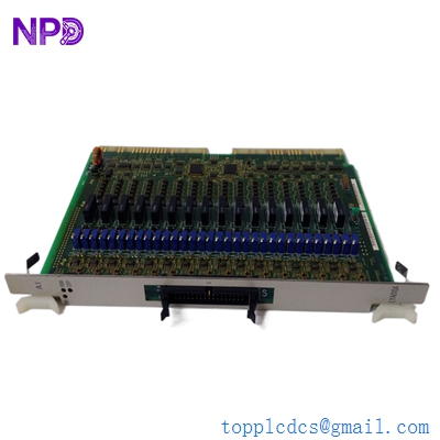
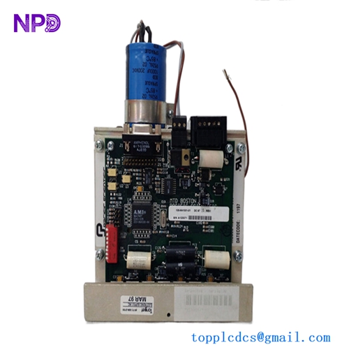
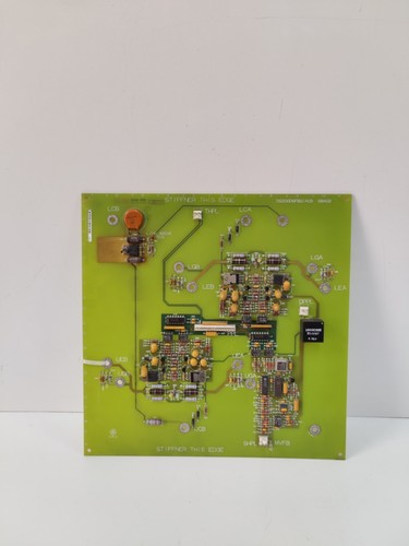
The GE DS200DSFBG1ACB is a high-precision Driver Shunt Feedback Board, a critical component within the Speedtronic Mark V gas turbine control system. This board is engineered to monitor and provide critical feedback on current signals within the turbine control loops, ensuring precise regulation of fuel systems and actuators. As part of the Mark V series, it is essential for maintaining the operational stability and safety of heavy-duty industrial turbines.
📋 Technical Specifications
🔹 Part Number: DS200DSFBG1ACB 🔹 System Series: Speedtronic Mark V (MKV) 🔹 Function: Driver Shunt Feedback / Current Monitoring 🔹 Operating Environment: Industrial Control Cabinet 🔹 Weight: Approximately 0.45 kg 🔹 Origin: United States
🚀 Application Fields
⚡ Gas Turbine Control Systems 🏭 Power Generation Plants ⚙️ Industrial Actuator Feedback Loops ⛽ Turbine Fuel Regulation Management
🛠️ Product Instructions
The DSFB board is designed for installation within a standard Mark V control rack. When installing, ensure the control system is powered down and that you are using appropriate ESD protection. Carefully align the board with the rack’s backplane connector. Ensure the board is fully seated to prevent intermittent signal loss, which can lead to turbine trips or unstable fuel control.
⚙️ Communication & Configuration Steps
⚙️ Address Mapping: This board functions as an analog feedback component. Address mapping is typically handled by the slot position within the Mark V rack (e.g., in the , , or controllers). ⚙️ Station Number: The board does not require a discrete network station ID; it is identified by the hardware configuration file defined in the Mark V “I/O Config” software. ⚙️ Scaling/Calibration: Calibration is managed through the Mark V “I/O Config” utility, where the shunt feedback values are mapped to the engineering units (e.g., Amps or percentage of full stroke) used by the turbine control software.
🔋 Power-up Debugging Process
✅ Step 1: Verify the stability of the 24V DC/±5V DC power rails in the control rack. ✅ Step 2: Insert the board and power up the rack; observe that the “OK” or “Active” diagnostic LEDs are illuminated. ✅ Step 3: Access the Mark V HMI or operator interface and verify that the feedback values from the corresponding actuator are reading within the expected nominal range. ✅ Step 4: Perform a “Signal Injection” test if necessary, using a calibrated current source to verify that the feedback signal matches the input.
📋 First-time Operation Checklist
✔️ Confirm the revision (G1ACB) matches the existing hardware for board-to-board compatibility. ✔️ Ensure the wiring harness connections to the shunt resistors are tight and free of oxidation. ✔️ Verify that no “Feedback Fault” or “Current Loop” alarms are present in the HMI alarm log. ✔️ Confirm that the turbine control loop is responding smoothly to manual position commands during the pre-start checks.
❓ Frequently Asked Questions (Q&A)
❓ Q: What should I do if I see a “Feedback Loop Fault” alarm? 💡 A: A feedback loop fault often points to a broken shunt wire, a disconnected harness, or a failing DSFB board. First, check the continuity of the cabling between the board and the external shunt resistor.
❓ Q: Can I replace this board while the turbine is running? 💡 A: The Mark V control system is designed for high availability, but hot-swapping critical feedback cards is inherently risky. Always consult your facility’s maintenance procedures and, if possible, perform the swap during a scheduled outage.
❓ Q: Why does the board have multiple adjustments/potentiometers? 💡 A: These are factory or field-calibration potentiometers used to fine-tune the gain and offset of the feedback signal. Only adjust these if you have the specific turbine calibration documentation and a calibrated signal source.