Description
Product Overview
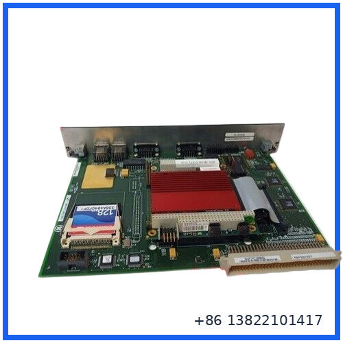
The GE IS215ACLEH1B is an Application Control Layer Module (ACLE) designed for GE EX2100 excitation control systems and associated Speedtronic turbine control applications. It functions as a microprocessor-based control layer, handling application software, system communication, and control processing rather than acting as a conventional field I/O module.
The module is installed in the control rack and interfaces with the system backplane. In EX2100 applications, the ACLE works as part of the excitation control architecture, where reliable processing and communication are important for generator voltage regulation and excitation-related functions.
The H1B version has its own firmware requirements. GE documentation specifically notes that firmware must be downloaded when an ACLE is replaced, so a simple physical board swap may not be sufficient for commissioning.
Main Features
- Application Control Layer Module for GE EX2100 excitation systems
- Microprocessor-based control architecture
- Designed for industrial excitation and turbine control environments
- Ethernet communication capability
- COM1 and COM2 serial interfaces
- 128 KB Level 2 cache
- 8 MB DRAM reported for the ACLE hardware
- Supports application and runtime software
- CompactFlash-based core load storage
- Rack-mounted construction
- Occupies two half-slots in the applicable EX2100/Innovation Series rack
- Firmware and application code can be loaded through the GE Control System Toolbox
- Suitable for replacement of aging or failed ACLE hardware when firmware and system compatibility are confirmed
Technical Specifications
| Parameter | Specification |
|---|---|
| Manufacturer | General Electric (GE) |
| Model | IS215ACLEH1B |
| Module Type | Application Control Layer Module (ACLE) |
| System | GE EX2100 Excitation Control |
| Application | Speedtronic / generator excitation control |
| Processor Architecture | Microprocessor-based |
| L2 Cache | 128 KB |
| DRAM | 8 MB |
| BIOS Flash | 4 MB reported |
| Communication | Ethernet |
| Serial Interfaces | COM1, COM2 |
| Backplane Interface | P1, 4-row 128-pin connector |
| Rack Position | Two half-slots |
| Configuration Software | GE Control System Toolbox |
| Core Operating System | QNX-based core load |
| Storage | CompactFlash |
| Functional Revision | H1B |
| System Firmware | Application-dependent |
| Installation | EX2100 / compatible Innovation Series control rack |
The 8 MB DRAM, 128 KB L2 cache, Ethernet, COM1/COM2 and two-half-slot architecture are consistently associated with the ACLE documentation. Exact memory/storage arrangements can vary with hardware revision, so the complete board identification should be checked before replacement.
Application Control Layer Function
The ACLE sits above the lower-level hardware and provides the processing environment for the control application.
A typical operating sequence is:
Control rack → ACLE processor → application/runtime software → excitation control functions → system communication
The module can run core software, runtime code and application-specific PCODE. The GE documentation explains that the core load provides the operating environment and Ethernet/COM functionality, while runtime and application code provide the control-specific functions.
This makes the ACLE different from a simple terminal board or digital I/O card. When diagnosing an EX2100 system, problems involving firmware, Ethernet communication, processor startup, or application execution can all involve the ACLE.
Firmware and Configuration
One of the most important points when replacing an IS215ACLEH1B is firmware compatibility.
GE documentation states that an ACLE replacement requires a firmware download. For the H1B version, the documented minimum firmware levels include:
- Thyristor Control: V11.50.02C
- Regulator Control: V04.50.02C
The GE Control System Toolbox is used for ACLE configuration and firmware/application downloads. Ethernet port ENET1 is used for runtime and application code loading, while the serial loader can be used during initial startup procedures.
Do not assume that installing a physically identical board automatically restores operation. Before replacement, record the existing firmware, application data and system configuration whenever possible.
Installation & Replacement Guide
1. Before Removal
Record:
- Complete board part number
- Functional revision
- Serial number
- Existing firmware version
- Application configuration
- Ethernet settings
- Connector locations
- LED status
- Any active system alarms
2. Remove the Existing Module
Follow the plant’s approved electrical isolation and turbine/excitation maintenance procedure. Disconnect the applicable cables and remove the board from the rack without forcing the backplane connector.
3. Install the Replacement
Check that the replacement board matches:
- IS215ACLEH1B identification
- Hardware revision
- Backplane arrangement
- System application
- Firmware requirements
Seat the module carefully into the rack and ensure that the P1 connector is correctly aligned.
4. Reload Firmware
After hardware installation, use the GE Control System Toolbox to load the required firmware and application software.
5. Commission the System
Verify:
- Processor startup
- LED indications
- Ethernet communication
- Serial communication where applicable
- Application code status
- Excitation controller communication
- System alarms
- Regulator operation
Perform final testing according to the site commissioning procedure before returning the excitation system to normal service.
Inspection Before Installation
For a replacement or surplus board, check the following first:
Physical condition
Look for damaged connectors, bent pins, cracked PCB areas, corrosion, overheated components or loose hardware.
Memory and storage
Inspect the CompactFlash/storage area and processor board for signs of physical damage.
Connector condition
Pay particular attention to the P1 backplane connector and communication connectors. Poor contact can produce intermittent startup or communication problems.
Revision identification
Do not rely only on the basic model number. Compare the complete GE board identification and revision marking with the board being replaced.
Troubleshooting
Module does not start
Check rack seating, backplane connection, power supply condition and processor/diagnostic indicators. If the hardware starts but the application does not run, verify the installed core load, runtime code and application code.
Ethernet communication failure
Check the Ethernet cable, network configuration and controller-side communication. Confirm that the correct application software and Ethernet parameters have been loaded.
Replacement board starts but control application does not operate
This is commonly a configuration or firmware compatibility issue rather than a simple hardware problem. Reload the appropriate firmware and application data using the GE Control System Toolbox.
Unexpected behavior after replacement
Compare the new module’s hardware revision and firmware level with the original unit. The H1B version has defined firmware requirements, so matching only the physical part number is not enough.
Typical Applications
The IS215ACLEH1B is associated primarily with GE excitation and turbine-control environments, including:
- Gas turbine generator systems
- Steam turbine generator systems
- Generator excitation control
- Automatic voltage regulator systems
- EX2100 excitation control cabinets
- Legacy GE Speedtronic control installations
- Industrial power-generation equipment
- Replacement and maintenance of existing GE control systems
A technical discussion specifically identifies the H1B as an Application Control Layer board for the GE EX2100 excitation system, while GE-related documentation identifies the ACLE family with EX2100 control hardware.
Maintenance Recommendations
Keep the control cabinet clean and dry. Avoid excessive dust accumulation around ventilation openings and processor hardware.
During scheduled maintenance:
- Check board seating
- Inspect connectors
- Record firmware versions
- Back up application configuration
- Check Ethernet communication
- Review diagnostic LEDs
- Check for abnormal temperature or discoloration
- Keep a known-good spare available for critical systems
For long-term storage, use ESD protection and keep the board in a controlled, dry environment.
FAQ
Q: What is the IS215ACLEH1B?
A: It is a GE Application Control Layer Module used primarily in EX2100 excitation control architecture.
Q: Is it a digital I/O module?
A: No. It is a processor/control-layer module rather than a conventional field I/O card.
Q: Can I install a replacement without configuring it?
A: Not necessarily. GE documentation specifies that firmware must be downloaded when an ACLE is replaced.
Q: What software is used to configure the ACLE?
A: GE Control System Toolbox is used for ACLE configuration, firmware upgrades and application-code downloads.
Q: Is IS215ACLEH1B related to IS215ACLAH1A?
A: Yes. They belong to the same Application Control Layer family, but the exact replacement relationship depends on hardware revision and firmware compatibility. Do not substitute one solely based on similar appearance or function.
Related GE Models
- IS215ACLAH1A
- IS215ACLEH1A
- IS215ACLEH1AB
- IS215ACLEH1AC
- IS215ACLEH1B
- IS215ACLEH2A
- IS200TBTCH1CBB
- IS200TFBAH1ACB
- IS200TREGH1AAA
- IS205SVMAG2ABB
Product Summary
The GE IS215ACLEH1B is a specialized Application Control Layer Module for GE EX2100 excitation control systems. Its role is centered on processor-based control execution, communication and application software rather than direct field signal termination.
For replacement projects, the key points are complete part-number matching, hardware revision, firmware level, application code and GE Control System Toolbox configuration. These checks should be completed before putting a replacement board into an operating turbine or generator control system.