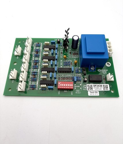


Description
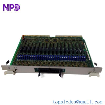
The GUTOR 0P0282 is an electronic power-supply board used in GUTOR industrial UPS systems. The associated identification is 21469-3 / 640-0398 Rev.03.
Available technical records identify 0P0282 as a 400 VDC power supply with outputs of +20 VDC, ±12 VDC, and +5 VDC, referenced as A202 in GUTOR system documentation.
This board provides low-voltage auxiliary power for associated control electronics. It is a system-specific UPS power-supply assembly and should be matched with the original GUTOR equipment before replacement.
📊 Product Datasheet
| Parameter | Specification |
|---|---|
| Brand | GUTOR |
| Model | 0P0282 |
| Series | GUTOR UPS / PEW Power System |
| Product Name | PCB Power Supply Board |
| Part Number | 21469-3 / 640-0398 |
| Revision | Rev.03 |
| Board Type | Electronic Power Supply Board |
| System Reference | A202 |
| Input | 400 VDC |
| Output | +20 VDC / ±12 VDC / +5 VDC |
| Application | Industrial UPS Control Power Supply |
| Product Status | Legacy / Maintenance Spare |
| Dimensions | Configuration-dependent |
| Weight | Approximately 1 kg according to a product record for 0P0282 |
| Country of Origin | Not verified |
The 400 VDC input and +20 VDC / ±12 VDC / +5 VDC outputs are specifically listed for GUTOR 0P0282 in system spare-parts documentation.
The exact dimensions, output-current capacity, efficiency, protection thresholds, and connector pinout should be verified from the original board and system documentation before commissioning.
⚙️ Main Features
🔹 GUTOR industrial UPS power-supply PCB
🔹 Model 0P0282
🔹 Part number 21469-3 / 640-0398
🔹 Revision Rev.03
🔹 400 VDC input configuration
🔹 Multiple auxiliary DC outputs
🔹 +20 VDC output
🔹 ±12 VDC output
🔹 +5 VDC output
🔹 GUTOR system reference A202
🔹 Designed for control and auxiliary electronics
🛠️ Operating Procedure & How to Use
The 0P0282 is designed to supply auxiliary control power within a compatible GUTOR UPS system. It should not be connected directly to a 400 VDC source for a simple bench test.
Before installation:
- Confirm 0P0282 on the original board.
- Verify 21469-3 / 640-0398.
- Confirm Rev.03 where applicable.
- Check the original UPS model.
- Record the board position and system reference.
- Photograph all connectors and wiring.
- Verify the input and output configuration.
- Shut down the UPS according to the approved procedure.
- Isolate all AC and DC energy sources.
- Verify that the high-voltage DC bus is discharged.
- Use appropriate PPE and ESD protection.
- Install the replacement PCB.
- Reconnect all wiring correctly.
- Check polarity and connector seating.
- Inspect the board for damage before energizing.
- Restore power according to the GUTOR startup procedure.
- Measure the auxiliary output voltages.
- Check the UPS controller and system alarms.
🔌 Startup Sequence
⚠️ The 400 VDC input makes this a high-voltage power-supply assembly. Qualified electrical personnel should perform installation and testing.
- Confirm the PCB is correctly mounted.
- Check all input and output connections.
- Verify DC polarity.
- Confirm grounding and protective connections.
- Ensure associated loads are correctly connected.
- Restore the control system according to the GUTOR procedure.
- Energize the appropriate DC supply section.
- Monitor the board during initial energization.
- Verify the +20 VDC output.
- Verify the +12 VDC and -12 VDC outputs.
- Verify the +5 VDC output.
- Check for excessive heating, noise, or abnormal odor.
- Check UPS controller status.
- Check for power-supply or system alarms.
- Confirm stable operation before returning the UPS to normal service.
⏹️ Shutdown Sequence
- Place the UPS in the approved safe operating condition.
- Follow the normal GUTOR shutdown procedure.
- Isolate the relevant AC supply.
- Isolate the high-voltage DC source.
- Apply lockout/tagout procedures.
- Verify that the 400 VDC bus is de-energized.
- Allow capacitors and other stored-energy components to discharge.
- Measure the DC bus before touching the PCB.
- Disconnect the board wiring.
- Remove the PCB carefully.
- Store the board in an ESD-safe package.
Do not remove or install the 0P0282 while the 400 VDC supply is energized.
📖 Product Usage Notes
The 0P0282 is particularly important because it provides the auxiliary voltages required by other electronics in the UPS system.
GUTOR system documentation lists the board as:
🔋 PSU 400VDC
⚡ Output: +20VDC / ±12VDC / +5VDC
📍 Reference: A202
The same system documentation identifies the 0P0282 alongside GUTOR controller and signal-control boards, confirming its role as part of the wider UPS control architecture.
When troubleshooting the board, measure the output rails only with appropriate equipment and according to the system test procedure.
A missing +5 VDC rail, for example, does not necessarily mean the PCB itself is defective. The fault may originate from the input supply, protection circuit, connector, downstream load, or another component in the UPS control system.
🔧 Maintenance Recommendations
🔍 Inspect the PCB for burnt components and discoloration.
⚡ Check input and output terminals for loose connections.
🌡️ Monitor abnormal heating.
🔌 Inspect connectors for corrosion or oxidation.
📏 Verify output voltages against the approved system specifications.
🧹 Keep the cabinet and ventilation paths clean.
📋 Record the board number and revision before replacement.
Do not increase fuse ratings or bypass protection devices to keep the board operating. A repeated fuse failure should be treated as a fault requiring investigation.
❓ Common Questions & Answers
Q: What is the GUTOR 0P0282?
A: It is a GUTOR electronic power-supply board used in industrial UPS systems.
Q: What is the part number?
A: The referenced identification is 21469-3 / 640-0398, with the supplied unit identified as Rev.03. The current listing also identifies the model as 0P0282.
Q: What is the input voltage?
A: GUTOR system records identify 0P0282 as a 400 VDC PSU.
Q: What are the output voltages?
A: The documented outputs are +20 VDC, +12 VDC, -12 VDC, and +5 VDC.
Q: What is the system reference?
A: The board is identified as A202 in GUTOR spare-parts documentation.
Q: Is 0P0282 a general-purpose 400 VDC power supply?
A: No. It is a GUTOR system-specific UPS power-supply assembly.
Q: Can I bench-test it with 400 VDC?
A: Not without the proper GUTOR test procedure. The board has multiple outputs and system-dependent connections and protection circuits.
Q: Can 0P0282 replace 0P0284?
A: No automatic substitution should be assumed. GUTOR documentation identifies 0P0282 for 400 VDC systems and 0P0284 for 220 VDC systems.
Q: What should I check before purchasing?
A: Confirm 0P0282, 21469-3 / 640-0398, revision, input voltage, output configuration, connectors, and the original UPS model.
Q: What are the main safety concerns?
A: The 400 VDC input presents a serious electrical hazard. Proper isolation, discharge verification, lockout/tagout, and qualified personnel are required.
Q: What if the output voltage is missing?
A: Check the input supply, fuses/protection, connectors, downstream load, and individual output circuits before concluding that the PCB has failed.
🔎 Recommended GUTOR Related Models & Modules
- GUTOR 0P0282 / 21469-3 / 640-0398 — 400 VDC Power Supply Board
- GUTOR 0P0284 — 220 VDC Power Supply
- GUTOR 0P0285 — 110/125 VDC Power Supply
- GUTOR 0P0280 — AC Supply PCB
- GUTOR 0P0363 / 640-0573 — Signal Controller PCB
- GUTOR 0P2446 / 640-1017 — Main Processor Board
- GUTOR 0P2447 / 640-1017 — Main Processor Board
- GUTOR 0P2438 / 21364-1 — Fan Monitor Board
- GUTOR 0P9910 — Interface Fuse Board
- GUTOR 0P2556B / 640-2556B — Interface Card / PSU Relay PCB