Description
⚙️ Product Introduction
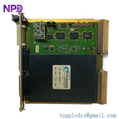
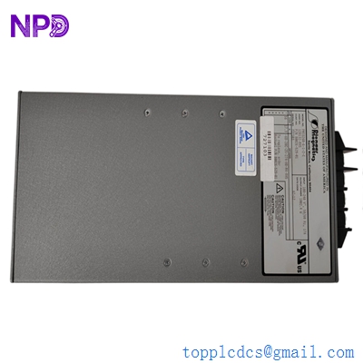
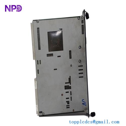
The GUTOR 0P0282 is an industrial power-supply PCB used in GUTOR UPS equipment. Available GUTOR spare-parts references identify 0P0282 as a 400 VDC input PSU providing +20 VDC, ±12 VDC, and +5 VDC outputs.
The supplied identification also shows 21469-3 / 640-0398 Rev.03. A current industrial listing identifies the same combination as a Gutor 0P0282 PCB Board, 21469-3 / 640-0398 Rev.03.
This board is intended for GUTOR UPS/power-system applications and should be replaced by matching the complete part number, PCB revision, connectors, and system configuration.
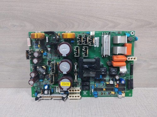
0P0282
📋 Product Datasheet
| Parameter | Specification |
|---|---|
| Brand | GUTOR |
| Model | 0P0282 |
| Series | GUTOR Industrial UPS |
| Product Name | PSU PCB Board |
| PCB / Assembly Reference | 21469-3 / 640-0398 |
| Revision | Rev.03 |
| Product Type | DC Power Supply PCB |
| Input Voltage | 400 VDC |
| Output Voltage | +20 VDC / ±12 VDC / +5 VDC |
| Application | GUTOR UPS Power System |
The 400 VDC input and +20 VDC / ±12 VDC / +5 VDC output configuration is specifically listed for GUTOR 0P0282.
⚠️ Exact output current, total power rating, dimensions, weight, connector pinout, protection thresholds, and component-level specifications were not reliably established from the available references and should be verified from the physical board or original GUTOR documentation.
🔧 Operating Standards & How to Use
🔹 Confirm 0P0282 and 21469-3 / 640-0398 Rev.03 before installation.
🔹 Verify that the host UPS system uses the 400 VDC input configuration.
🔹 Compare the replacement board with the original board before removing the old unit.
🔹 Check all connectors and terminal positions carefully.
🔹 Use ESD protection when handling the PCB.
🔹 Inspect capacitors, transformers, connectors, and power components for damage.
🔹 Verify polarity and wiring before energizing.
🔹 Do not apply an external voltage to the board unless the correct connection and test procedure are known.
⚠️ This is a high-voltage DC power-supply board. The 400 VDC input specification means the circuit can present a serious electrical hazard.
▶️ Startup Sequence
- 🔍 Confirm the board model and revision.
- 🧰 Inspect PCB condition and connectors.
- 🔌 Check all wiring against the original installation.
- 🛡️ Verify grounding and protective devices.
- ⚡ Restore the GUTOR system power according to its approved procedure.
- 📊 Verify the DC input voltage.
- 🔎 Check the +20 VDC, +12 VDC, -12 VDC, and +5 VDC supply rails.
- 🖥️ Check UPS controller indications and alarms.
- 🧪 Perform a controlled functional test.
- 📈 Monitor the UPS system for abnormal voltage, temperature, or alarms.
⏹️ Shutdown Sequence
- Stop the UPS/load system using the normal shutdown procedure.
- Place the equipment into the approved maintenance or bypass condition.
- Isolate the relevant AC and DC power sources.
- Apply lockout/tagout procedures.
- Verify the absence of hazardous voltage with suitable test equipment.
- Allow stored electrical energy to discharge according to the manufacturer’s procedure.
- Remove the PCB using ESD precautions.
- Install the replacement only after the circuit is confirmed safe.
⚠️ Do not assume that switching off the main supply immediately makes a UPS DC circuit safe. Stored energy may remain in capacitors and other components.
📘 Product Usage Instructions
The 0P0282 is a multi-output auxiliary power-supply PCB within the GUTOR UPS architecture.
A simplified relationship is:
400 VDC Input → GUTOR 0P0282 PSU → +20 VDC / ±12 VDC / +5 VDC → Control & Electronic Circuits
The different output rails can supply different electronic sections of the UPS system. The exact distribution depends on the particular GUTOR equipment configuration.
For replacement work, record the original PCB position, connector arrangement, wiring, revision, and any jumper or configuration settings before removal.
After installation, verify each available output rail before returning the UPS to normal operation.
🛠️ Installation & Maintenance
🔹 Keep the PCB clean and dry.
🔹 Store it in an ESD-safe package.
🔹 Avoid touching connector contacts and component pins.
🔹 Inspect electrolytic capacitors for leakage, swelling, or discoloration.
🔹 Check high-voltage components for overheating.
🔹 Inspect solder joints and PCB traces.
🔹 Check connectors for oxidation or looseness.
🔹 Verify all output rails after replacement.
🔹 Record the PCB revision in the maintenance log.
🔹 Perform a complete UPS functional test after installation.
❓ Common Questions & Answers
Q: What is GUTOR 0P0282?
A: It is a GUTOR UPS power-supply PCB. GUTOR spare-parts references identify it as a 400 VDC PSU with +20 VDC, ±12 VDC, and +5 VDC outputs.
Q: What is the input voltage?
A: The specified input is 400 VDC.
Q: What are the output voltages?
A: The listed outputs are +20 VDC, +12 VDC, -12 VDC, and +5 VDC.
Q: What is 21469-3 / 640-0398?
A: These are additional board/assembly identification references associated with the supplied 0P0282 PCB. An industrial listing specifically identifies the board as 0P0282, 21469-3 / 640-0398 Rev.03.
Q: Is 0P0282 a complete UPS?
A: No. It is a power-supply PCB used as a component within a GUTOR UPS system.
Q: Can it be used as a general-purpose 400 VDC power supply?
A: It should not be treated as a generic PSU. The multiple dedicated output rails and system-specific connectors indicate that it is intended for compatible GUTOR equipment.
Q: Is 0P0282 the same as 0P0280?
A: No. GUTOR references identify 0P0280 as a complete PCB PSU AC supply, while 0P0282 is the 400 VDC-input PSU with +20 VDC / ±12 VDC / +5 VDC outputs.
Q: Can 0P0282 replace another GUTOR PSU?
A: Not automatically. Input voltage, output rails, current capacity, connectors, mounting, and UPS configuration must all match.
Q: Is the Rev.03 version important?
A: Yes. For legacy equipment, the PCB revision should be matched whenever possible because component layouts or circuit revisions can differ.
Q: What should I check before purchasing?
A: Confirm GUTOR 0P0282, 21469-3 / 640-0398, Rev.03, PCB condition, connector arrangement, and the required 400 VDC / multi-output configuration.
⭐ Recommended GUTOR Related Series & Models
- GUTOR 0P0282 — 400 VDC PSU PCB
- GUTOR 0P0280 — AC Supply PCB
- GUTOR 0P0284 — 220 VDC PSU
- GUTOR 0P0363 — Signalis Controller
- GUTOR 0P2439 — Masterlogic II PCB Assembly
- GUTOR 0P2446 — XXW PCB Controller
- GUTOR 0P2447 — XXW PCB Controller
- GUTOR 0P2405 — FC UPS Interface Fuse
- GUTOR 0P2407 — FC UPS Interface Fuse
- GUTOR SILCON Series — Industrial UPS System
These are related GUTOR spare parts and system components, not confirmed direct replacements for 0P0282. The available spare-parts documentation distinguishes the 400 VDC 0P0282 from the 220 VDC 0P0284 and the AC-supply 0P0280.
📦 Replacement Identification
For purchasing and maintenance records, use the complete identification: