

Description
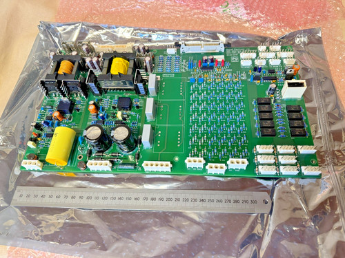
The GUTOR 0P0285 is an industrial PCB used in GUTOR UPS equipment. Product records identify the 0P0285 as a power regulation component / circuit board, making it part of the internal power-control section of a GUTOR UPS system.
The board is associated with legacy GUTOR industrial UPS equipment and is intended for system-specific installation. Because internal GUTOR boards can have different revisions and electrical functions, the complete part number and PCB markings should be checked before replacement.
The referenced listing identifies the unit as GUTOR 0P0285 PCB, with the listed condition being New – Open Box.
📋 Product Datasheet
| Parameter | Value |
|---|---|
| Brand | GUTOR |
| Model | 0P0285 |
| Series | GUTOR Industrial UPS |
| Product Name | PCB Power Regulation Component |
| Product Type | Industrial Circuit Board |
| Main Function | Power Regulation / Control Interface |
| Application | Industrial UPS |
| Mounting | Internal UPS Chassis |
| PCB Type | Electronic Control / Power PCB |
| Condition | New – Open Box |
| Country of Origin | Not confirmed |
| Dimensions | Not specified |
| Weight | Not specified |
| Input Voltage | Host-system dependent |
| Power Rating | Host-system dependent |
The available product information identifies 0P0285 as a power regulation component/circuit board and gives HS classification 85049090.
⚠️ Exact voltage, current, power rating, dimensions, weight, connector pinout, and environmental specifications should be verified from the physical PCB and the corresponding GUTOR equipment documentation. These values should not be estimated for electrical installation.
⚙️ Operating Guidelines
🔹 Confirm the complete part number 0P0285 before installation.
🔹 Check the PCB revision and any additional suffix printed on the board.
🔹 Compare connector positions, terminal arrangement, mounting holes, and PCB layout with the original board.
🔹 Verify compatibility with the specific GUTOR UPS cabinet.
🔹 Inspect the PCB for oxidation, damaged components, cracked solder joints, burned areas, and damaged connectors.
🔹 Use ESD protection during handling.
🔹 Check the condition of electrolytic capacitors before commissioning, particularly when dealing with long-stored surplus stock.
🔹 Do not install or remove the PCB from an energized UPS system.
🛠️ How to Use
- 🔍 Record the original PCB model and revision.
- ⚡ Shut down the GUTOR UPS using the normal operating procedure.
- 🔌 Isolate all applicable AC and DC/battery power sources.
- 🔒 Apply the required lockout/tagout procedure.
- ⏳ Allow the internal DC bus and capacitors to discharge.
- 🧪 Verify the absence of hazardous voltage with appropriate test equipment.
- 🧤 Wear suitable ESD protection.
- 🧩 Remove the existing PCB carefully.
- 🔧 Install the GUTOR 0P0285 in the correct mounting position.
- 🔗 Reconnect all cables and connectors according to the original configuration.
- 🔍 Check polarity, connectors, mounting, and wiring.
- ⚡ Restore power following the UPS startup procedure.
- 🚨 Check system alarms and fault indicators.
- 📊 Verify stable UPS operation.
- ✅ Perform a controlled functional test before returning the equipment to service.
🔌 Power-On Sequence
- 🔍 Inspect the installed 0P0285 PCB.
- 🧰 Confirm correct mechanical installation.
- 🔗 Verify all connectors and wiring.
- 🔋 Restore the required auxiliary/DC supply.
- ⚡ Energize the UPS input according to the system procedure.
- ⏳ Allow the control electronics to initialize.
- 🖥️ Check the UPS control panel.
- 🚨 Check for power-supply or PCB-related alarms.
- 📊 Verify normal voltage and system status.
- ✅ Return the UPS to normal operating mode.
⛔ Power-Off Sequence
- Notify the responsible operator.
- Place the protected load in a safe condition.
- Shut down the UPS normally.
- Isolate the AC input.
- Isolate the battery/DC source.
- Apply lockout/tagout.
- Wait for the required discharge time.
- Verify that hazardous voltage is absent.
- Remove the 0P0285 PCB only after complete electrical isolation.
⚠️ Industrial UPS systems can contain dangerous stored energy even after the main input has been switched off. PCB replacement should be performed by qualified electrical or UPS service personnel.
📘 Product Usage Notes
The GUTOR 0P0285 is best treated as a system-specific UPS PCB, not as a universal power-supply board.
A separate market listing identifies a related 0P0285/2.1 640-0398 circuit-board version, showing that revision and additional part-number information can be important when sourcing replacement units.
For procurement, compare:
- 0P0285
- PCB revision
- Additional PCB part number
- Connector configuration
- Mounting dimensions
- Original UPS model
- Existing board markings
- Electrical rating
Do not select a replacement solely because the PCB has the same physical size or similar appearance.
❓ Common Questions & Answers
Q: What is GUTOR 0P0285?
A: It is an industrial GUTOR UPS circuit board used as a power regulation component/control PCB.
Q: What is the main function?
A: Available product information identifies it as a power regulation component and circuit board for GUTOR UPS applications.
Q: Is 0P0285 a PLC CPU?
A: No. It is a dedicated GUTOR UPS PCB rather than a general-purpose PLC processor.
Q: What equipment is it used in?
A: It is used in GUTOR industrial UPS equipment.
Q: Can another 0P0285 revision be used as a replacement?
A: Not automatically. The exact revision, PCB assembly number, electrical characteristics, and host UPS configuration should be checked.
Q: Is the referenced unit new?
A: The supplied listing identifies the condition as New – Open Box.
Q: Does the board have a standalone power rating?
A: A reliable standalone power rating is not established from the available identification. The rating depends on the host GUTOR system.
Q: Can it be hot-swapped?
A: Hot-swapping should not be assumed. The UPS should be shut down and electrically isolated before removing the PCB.
Q: Does 0P0285 require configuration?
A: Any system-specific configuration depends on the host GUTOR UPS. The replacement should be compared with the original board before commissioning.
Q: What should I check before purchasing?
A: Check 0P0285, revision markings, any secondary part number such as 640-0398, connector layout, and the exact UPS model.
Q: What is the recommended storage method?
A: Store the PCB in an ESD-safe bag in a clean, dry environment away from condensation, dust, vibration, and excessive temperature.
⭐ Recommended Other GUTOR Models / Parts
- GUTOR 0P0010 | Control Circuit Board
- GUTOR 0P0280 | PCB Circuit Board
- GUTOR 0P0285 | Power Regulation PCB
- GUTOR 0P1922 | Parallel Operation Controller PCB
- GUTOR 0P2405A | Interface Fuse Board
- GUTOR 0P2447 | Main Processor Board
- GUTOR 0P2552 | Power Connection Board
- GUTOR 0P2560A | Static Switch Controller Board
- GUTOR 21108-2 | Voltage Supply Board
- GUTOR UNC1X-0P-00088 | PCA SDC Interface Card