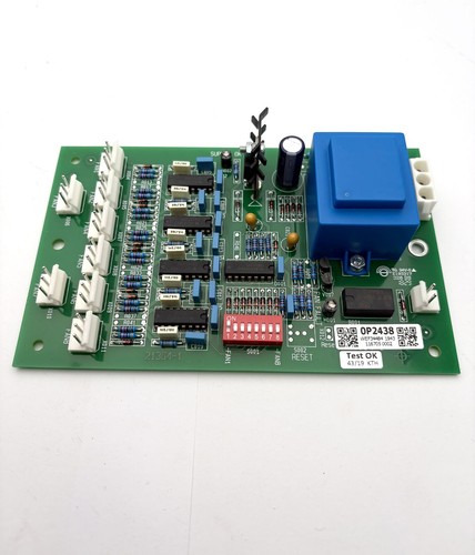


Description
The GUTOR 0P0363 is a GUTOR industrial control PCB identified by part number 640-0573. It is associated with GUTOR UPS and power-control equipment and is intended to operate as part of the system’s control and interface architecture.
For replacement applications, the complete board identification should be checked carefully, including 0P0363, 640-0573, revision markings, connector arrangement, and the original GUTOR equipment model.
This is a system-specific industrial PCB rather than a universal controller. Proper installation requires compatibility with the associated GUTOR hardware and control configuration.

📊 Product Datasheet
| Parameter | Specification |
|---|---|
| Brand | GUTOR |
| Model | 0P0363 |
| Series | GUTOR UPS / Power System |
| Product Name | PCB Control Board |
| Part Number | 640-0573 |
| Board Type | Industrial Control PCB |
| Application | UPS / Power Control |
| System Function | Control / Interface |
| Manufacturer | GUTOR |
| Product Status | Legacy / Maintenance Spare |
| Power Supply | System-dependent |
| Operating Voltage | System-dependent |
| Communication | System-dependent |
| Dimensions | Configuration-dependent |
| Weight | Configuration-dependent |
| Country of Origin | Not verified |
⚠️ Exact electrical ratings, I/O functions, dimensions, communication interfaces, and firmware specifications should be verified against the original GUTOR system documentation and the identification labels on the actual PCB.
⚙️ Main Features
🔹 GUTOR industrial control PCB
🔹 Model 0P0363
🔹 Part number 640-0573
🔹 Designed for integration into GUTOR UPS/power equipment
🔹 System-level control/interface function
🔹 Suitable for legacy equipment maintenance
🔹 Compact PCB construction
🔹 Intended as a replacement component for compatible GUTOR systems
🛠️ Operating Procedure & How to Use
The 0P0363 should be installed only in the GUTOR system for which it is specified. Do not connect the board to an external power supply simply to test whether it operates.
Before installation:
- Verify the board marking 0P0363.
- Confirm part number 640-0573.
- Compare the PCB layout with the existing board.
- Check revision markings.
- Photograph all connectors before removal.
- Record the original board position.
- Record the associated GUTOR UPS model.
- Shut down the equipment according to the approved procedure.
- Isolate AC and DC power sources.
- Verify the absence of hazardous voltage.
- Use ESD protection when handling the PCB.
- Install the replacement board in the correct position.
- Reconnect all wiring according to the original configuration.
- Inspect connectors and terminals.
- Restore power following the GUTOR startup procedure.
- Check alarms, status indicators, communication, and system operation.
🔌 Startup Sequence
⚠️ GUTOR UPS equipment may contain hazardous AC and DC energy. Qualified personnel should perform installation and commissioning.
- Confirm the system is mechanically complete.
- Verify that the 0P0363 is correctly installed.
- Check all connectors and cables.
- Verify grounding and control connections.
- Restore control power according to the equipment procedure.
- Allow the control system to initialize.
- Check board/system status indications.
- Verify communication with associated control boards.
- Check active alarms.
- Confirm normal UPS control functions.
- Test relevant operating commands and feedback signals.
- Return the equipment to service only after the system passes the required functional checks.
⏹️ Shutdown Sequence
- Place the UPS in the approved safe operating condition.
- Follow the normal GUTOR shutdown procedure.
- Isolate the applicable AC supply.
- Isolate the DC/battery supply where required.
- Apply lockout/tagout procedures.
- Verify the DC bus and other relevant circuits are de-energized.
- Allow stored energy to discharge.
- Verify safe voltage levels with suitable test equipment.
- Remove the PCB only after complete isolation.
- Store the removed board in an ESD-safe package.
Do not remove or insert the 0P0363 while the equipment is energized unless the specific GUTOR service documentation explicitly authorizes live replacement.
📖 Product Usage Notes
When replacing an older GUTOR PCB, physical fit alone is not enough to establish compatibility.
Record the following information from the original installation:
🔍 Model number
🔍 Part number
🔍 Revision
🔍 Board position
🔍 UPS model
🔍 Connector layout
🔍 Cable arrangement
🔍 Firmware or software information
🔍 Associated control modules
If the replacement PCB has a different revision, compare the component layout and system documentation before installation. A visually similar GUTOR PCB may have a different function or electrical configuration.
🔧 Maintenance Recommendations
🧹 Keep the PCB and cabinet free from dust and conductive contamination.
🔌 Inspect connectors for oxidation or loose contacts.
🌡️ Check for abnormal heat around power components.
🔍 Look for burnt components, cracked solder joints, corrosion, or damaged terminals.
⚡ Verify that the associated power supply is within the specified system range.
📋 Record board identification before removing the original unit.
If the UPS produces an alarm after installing the board, check wiring, power supplies, communication connections, configuration, and associated modules before assuming that the PCB itself has failed.
❓ Common Questions & Answers
Q: What is the GUTOR 0P0363?
A: It is a GUTOR industrial PCB identified by part number 640-0573, designed for use within GUTOR UPS/power-control equipment.
Q: What is the part number?
A: The referenced part number is 640-0573.
Q: Is 0P0363 a standalone PLC?
A: No. It is a system-specific GUTOR PCB intended to operate as part of compatible power-control equipment.
Q: What does the 640-0573 number identify?
A: It is the board’s associated part/assembly identification.
Q: Can I power the PCB on a workbench?
A: This should not be attempted without the correct GUTOR test procedure, because the required supply voltage, control signals, connected modules, and protection circuits are system-dependent.
Q: Can another GUTOR PCB replace 0P0363?
A: Not automatically. The complete part number, revision, connector arrangement, electrical function, and UPS configuration must match.
Q: What should I check before ordering?
A: Confirm 0P0363, 640-0573, revision marking, board layout, connector positions, and the original GUTOR equipment model.
Q: Can this board be hot-swapped?
A: Do not assume that it can. Normal maintenance practice is to isolate the equipment before removing or installing a control PCB unless the manufacturer’s procedure specifically permits live replacement.
Q: What are the main installation risks?
A: Incorrect wiring, incompatible hardware, ESD damage, and residual AC/DC voltage are the main concerns.
Q: Is this suitable for legacy GUTOR equipment?
A: It can be suitable as a maintenance spare when the original equipment specifically requires 0P0363 / 640-0573. Compatibility should be confirmed before installation.
🔎 Recommended GUTOR Related Models & Modules
- GUTOR 0P0363 / 640-0573 — Control PCB
- GUTOR 0P2446 / 640-1017 — Main Processor Board
- GUTOR 0P2447 / 640-1017 — Main Processor Board
- GUTOR 0P2438 / 21364-1 — Fan Controller PCB
- GUTOR 0P9910 / 0021404 — Interface Fuse Board
- GUTOR 0P0280 — AC Power Supply Module
- GUTOR 0P0284 — DC Power Supply Module
- GUTOR 0P9914 — Adapter / Interface Board
- GUTOR 0P9917 — Interface / Control Board
- GUTOR 640-0573 Control PCB Series — Related GUTOR Control Hardware