

Description
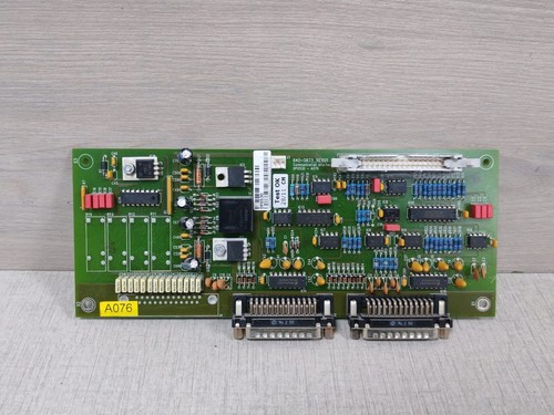
The GUTOR 0P0530-A076 is a communication interface PCB used in compatible GUTOR PEW/PDW UPS systems. GUTOR documentation identifies position A076 as the Communication Interface and specifies two serial RS232 outputs. The interface is installed in the low-voltage section of the UPS system.
GUTOR parts documentation identifies 0P0530 as a PCB Assembly COM Interface for GUTOR and AIS, while the supplied product identification adds 640-0673. A matching industrial listing identifies 0P0530-A076 / 640-0673 / Rev.01.
The communication interface is designed to exchange UPS operating information with external equipment. GUTOR documentation describes the interface as providing serial communication for interaction between the UPS and computer systems, including system-condition and measured-value information.

📋 Product Datasheet
| Parameter | Specification |
|---|---|
| Brand | GUTOR Electronics |
| Model | 0P0530-A076 |
| Series | GUTOR PEW / PDW UPS |
| Product Name | Communication Interface PCB |
| Part Number | 640-0673 |
| Revision | Rev.01 |
| Board Position | A076 |
| Communication Interface | 2 × Serial RS232 |
| Installation Section | Low-Voltage Section |
| Application | GUTOR UPS / Inverter Communication |
GUTOR documentation specifically confirms the A076 communication interface and its two serial RS232 outputs.
⚠️ Public documentation does not provide sufficiently reliable information for this exact board regarding dimensions, weight, input supply rating, power consumption, connector pinout, or detailed baud-rate configuration. Those values should be verified from the physical PCB and applicable system documentation.
🔧 Operating Standards & How to Use
🔹 Confirm the complete identification: 0P0530-A076 / 640-0673 / Rev.01.
🔹 Verify that the host UPS uses the A076 communication-interface position.
🔹 Check the existing board and connector arrangement before replacement.
🔹 Photograph all communication cables before removing the original PCB.
🔹 Use ESD protection when handling the board.
🔹 Verify RS232 cable connections and connector assignments.
🔹 Do not connect RS232 ports directly to Ethernet equipment.
🔹 If network monitoring is required, use the appropriate GUTOR communication/network architecture.
🔹 Check the UPS for communication alarms after installation.
GUTOR’s network-monitoring documentation shows the A076 Communication Interface connected with the UPS controller and, where applicable, additional Smart Slot Translator and Network Management Card equipment.
▶️ Startup Sequence
- 🔍 Verify 0P0530-A076 / 640-0673 and PCB revision.
- 🧰 Inspect the PCB and connectors.
- 🔌 Connect the RS232 cables according to the original configuration.
- 🛡️ Verify grounding and cabinet connections.
- ⚡ Restore UPS control power according to the system procedure.
- 💡 Check UPS status indicators.
- 🖥️ Verify communication with the connected computer or monitoring equipment.
- 🔄 Test the available RS232 communication channels.
- 📊 Confirm that UPS status and measured information are being received.
- 🧪 Monitor the system for communication alarms before returning it to normal service.
⏹️ Shutdown Sequence
- Place the UPS into the approved maintenance or bypass condition.
- Stop external monitoring or communication software if required.
- Isolate the relevant control power.
- Apply lockout/tagout procedures where required.
- Verify that the PCB is electrically safe to handle.
- Disconnect the RS232 cables.
- Remove the board using ESD precautions.
- Install the replacement PCB.
- Reconnect all communication cables.
- Restore power and perform a communication test.
⚠️ Do not assume this PCB is hot-swappable. Unless the applicable GUTOR equipment documentation explicitly permits live replacement, isolate power before removing the board.
📘 Product Usage Instructions
The 0P0530-A076 provides a serial communication path between the GUTOR UPS controller and external communication equipment.
A simplified arrangement is:
GUTOR UPS Controller A070 → Communication Interface A076 → RS232 → External Monitoring / Computer
GUTOR documentation states that the A076 interface provides two serial RS232 outputs. The broader communication architecture can also include a Smart Slot Translator and Network Management Card for network-based monitoring.
For replacement work:
🔹 Record the original connector positions.
🔹 Record cable labels.
🔹 Check the PCB revision.
🔹 Compare the replacement PCB layout with the original.
🔹 Restore cables exactly according to the original configuration.
🔹 Start the UPS and verify communication before placing the system back into normal service.
The A076 board should not be confused with the A074 Modbus protocol converter or A092 Network Management Card; GUTOR documentation identifies these as separate system components.
🛠️ Installation & Maintenance
🔹 Keep the PCB dry and clean.
🔹 Store it in an antistatic bag.
🔹 Avoid touching connector contacts and electronic components.
🔹 Inspect RS232 connectors for bent pins or oxidation.
🔹 Check communication cables for damage.
🔹 Make sure the PCB is properly secured.
🔹 Avoid excessive cable stress on the connectors.
🔹 Record the PCB revision during maintenance.
🔹 Check for communication alarms after installation.
🔹 Perform a communication test before returning the UPS to service.
❓ Common Questions & Answers
Q: What is GUTOR 0P0530-A076?
A: It is a GUTOR communication-interface PCB for compatible UPS systems.
Q: What is the part number?
A: The board is identified as 640-0673 in the supplied product information.
Q: What is the board position?
A: The communication interface is designated A076 in GUTOR system documentation.
Q: How many communication ports does it have?
A: GUTOR documentation specifies two serial RS232 outputs for the A076 communication interface.
Q: What is the purpose of the RS232 ports?
A: They provide serial communication between the UPS and external equipment such as a computer or monitoring system.
Q: Is this an Ethernet communication card?
A: No. The A076 interface itself is documented with serial RS232 outputs. Ethernet network monitoring can require additional GUTOR network-management hardware.
Q: Is 0P0530 the same family as 0P0530-A076?
A: Yes. GUTOR parts documentation identifies 0P0530 as the PCB assembly for the communication interface at A076.
Q: Is 640-0673 a replacement part number?
A: The supplied identification associates 640-0673 with 0P0530-A076. A matching industrial listing also identifies the board as 0P0530-A076, Rev.01.
Q: Can I replace it with another GUTOR communication board?
A: Not automatically. Connector configuration, revision, system architecture, and UPS compatibility must be checked.
Q: Can it be hot-swapped?
A: Do not assume so. Follow the specific GUTOR UPS maintenance procedure.
Q: What should I check before purchasing?
A: Confirm GUTOR 0P0530-A076, 640-0673, Rev.01, connector arrangement, PCB condition, and compatibility with the customer’s UPS.
⭐ Recommended GUTOR Related Series & Models
- GUTOR 0P0530-A076 — Communication Interface
- GUTOR 0P0530 — PCB Assembly Communication Interface
- GUTOR 0G-0399924A — Modbus RS232/RS485 Converter
- GUTOR 0P2420 — Network Management Card
- GUTOR 0P820-9604S — AP9604S PCB Assembly
- GUTOR 0P0363 — Signalling Controller A072
- GUTOR 0M-94035A — Front Panel Assembly
- GUTOR 0P9912A — 16-Relay Board
- GUTOR 0P2439A — MasterLogic II PCB Assembly
- GUTOR SILCON Series — Industrial UPS Systems
These are related GUTOR communication, control, monitoring, and UPS products. They are not confirmed direct replacements for 0P0530-A076. GUTOR’s own parts documentation distinguishes the A074 Modbus converter, A076 communication interface, A091 Smart Slot hardware, and A092 Network Management Card as separate components.