

Description
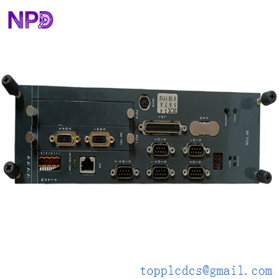
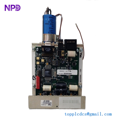
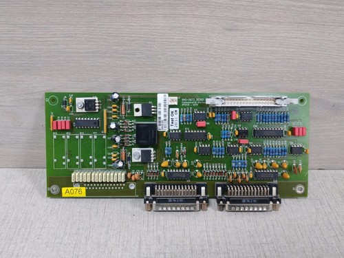
The GUTOR 0P0530-A076 is a communication interface board identified with part number 640-0673. It is designed for use within compatible GUTOR UPS and industrial power-system equipment.
The A076 designation is associated with the communication-interface position in GUTOR system architecture. The board is intended to provide serial communication between the UPS control system and external monitoring or communication equipment.
This is a system-specific industrial PCB rather than a general-purpose communication module. Before replacement, the complete part number, revision, connector arrangement, and host UPS model should be matched.
📋 Product Datasheet
| Parameter | Specification |
|---|---|
| Brand | GUTOR Electronics |
| Model | 0P0530-A076 |
| Series | GUTOR UPS / Industrial Power Systems |
| Product Name | Communication Interface |
| Part Number | 640-0673 |
| Product Type | Communication Interface PCB |
| System Position | A076 |
| Communication Function | Serial Communication Interface |
| Application | GUTOR UPS / Power Equipment |
| Product Status | Legacy / Replacement Spare |
⚠️ Exact supply voltage, dimensions, weight, connector pinout, baud rate, and detailed protocol specifications should be verified against the physical PCB and the applicable GUTOR system documentation. I would not recommend estimating these values for a replacement listing.
🔧 Operating Standards & How to Use
🔹 Confirm the board identification before installation: 0P0530-A076 / 640-0673.
🔹 Check the PCB revision and compare it with the existing board.
🔹 Verify that the customer’s GUTOR UPS uses the A076 communication-interface position.
🔹 Inspect all connectors for bent pins, oxidation, or mechanical damage.
🔹 Record the original cable positions before removing the old PCB.
🔹 Use ESD protection when handling the board.
🔹 Confirm communication wiring before restoring power.
🔹 Do not connect the interface to an external communication network until the interface type and wiring have been verified.
🔹 After installation, check the UPS communication and monitoring functions.
▶️ Startup Sequence
- 🔍 Confirm model, part number, and PCB revision.
- 🧰 Inspect the board and connectors.
- 🔌 Connect all communication cables according to the original wiring.
- 🛡️ Verify grounding and cabinet connections.
- ⚡ Restore UPS control power.
- 💡 Check UPS status indicators and alarms.
- 🖥️ Verify communication between the controller and external monitoring equipment.
- 🔄 Test each connected communication channel.
- 📊 Confirm that UPS status information is being transmitted correctly.
- 🧪 Complete a controlled system test before returning the UPS to normal service.
⏹️ Shutdown Sequence
- Place the UPS into the approved maintenance or bypass condition.
- Stop external monitoring or communication software where applicable.
- Isolate the relevant control power.
- Apply lockout/tagout procedures when required.
- Verify that the PCB is safe to handle.
- Disconnect communication cables.
- Remove the existing board using ESD precautions.
- Install the replacement board.
- Reconnect all cables.
- Restore power and perform a communication test.
⚠️ Do not assume this PCB supports hot-swapping. Unless the applicable GUTOR manual explicitly permits live replacement, power should be isolated before removing the board.
📘 Product Usage Instructions
The 0P0530-A076 is used as an interface between the GUTOR UPS control electronics and external communication equipment.
A simplified communication path is:
GUTOR UPS Controller → 0P0530-A076 → Serial Communication → Monitoring / Control Equipment
When replacing the board, the most important points are correct board identification and correct cable placement. Take photographs of the original installation before removal and record connector locations.
After installation:
🔹 Verify that the UPS controller starts normally.
🔹 Check for communication-related alarms.
🔹 Confirm the external monitoring system receives UPS status information.
🔹 Check event/alarm reporting.
🔹 Verify communication stability during normal UPS operation.
🛠️ Installation & Maintenance
🔹 Keep the PCB dry and free from conductive dust.
🔹 Store the board inside an ESD-safe package.
🔹 Avoid touching connector contacts.
🔹 Inspect connectors before installation.
🔹 Check the PCB for corrosion, cracked components, or burn marks.
🔹 Make sure communication cables are correctly seated.
🔹 Avoid excessive cable bending near the connectors.
🔹 Record the installed PCB revision in maintenance records.
🔹 Perform a communication test after replacement.
❓ Common Questions & Answers
Q: What is GUTOR 0P0530-A076?
A: It is a GUTOR communication-interface PCB for compatible UPS and industrial power-system equipment.
Q: What is the part number?
A: The board is identified as 640-0673.
Q: What does A076 mean?
A: A076 identifies the corresponding communication-interface position in the applicable GUTOR system architecture.
Q: Is this a power-supply board?
A: No. It is a communication interface board.
Q: Is this a PLC I/O module?
A: No. Its primary purpose is communication/interface functionality rather than standard analog or digital I/O.
Q: Can I use another GUTOR communication PCB as a replacement?
A: Not without verification. The communication hardware, connectors, system position, firmware, and host UPS configuration must be compatible.
Q: Can this board be hot-swapped?
A: Do not assume so. Follow the specific GUTOR equipment maintenance procedure.
Q: What should I check before buying?
A: Confirm 0P0530-A076, 640-0673, revision, connector arrangement, physical condition, and compatibility with the customer’s GUTOR UPS.
Q: Why is the PCB revision important?
A: Different revisions can contain hardware or component changes. For legacy GUTOR equipment, matching the original revision is preferable whenever possible.
Q: Can the board be used outside GUTOR equipment?
A: It should not be treated as a generic communication board. Its electrical interface and system integration are application-specific.
⭐ Recommended GUTOR Related Models
- GUTOR 0P0530-A076 — Communication Interface
- GUTOR 0P0530 — Communication Interface PCB Assembly
- GUTOR 0P0363 — Signalis Controller
- GUTOR 0P2420 — Network Management Card
- GUTOR 0P0280 — AC Supply PCB
- GUTOR 0P0282 — 400 VDC PSU PCB
- GUTOR 0P0284 — DC Power Supply PCB
- GUTOR 0P2439 — Masterlogic II PCB Assembly
- GUTOR 0P9912A — Relay Board
- GUTOR SILCON Series — Industrial UPS System
⚠️ These are related GUTOR products and are not confirmed direct replacements for 0P0530-A076. Electrical, mechanical, communication, and system compatibility should be checked before substitution.