

Description
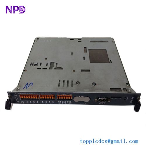
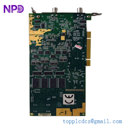
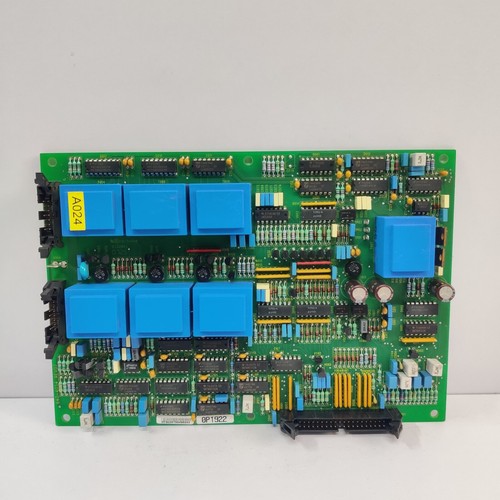
The GUTOR 0P1922 is a PCB Controller for Parallel Operation used in GUTOR UPS and power-conversion systems. GUTOR spare-parts records identify 0P1922 and 0P1922A specifically as “PCB Controller Parallel Operating.”
Its main purpose is to coordinate multiple UPS or Datapower systems operating in parallel. The controller handles synchronization, operating-mode coordination, and load sharing between connected systems. The documented 0P1922A specification states that up to 9 parallel systems can be controlled.
The supplied listing identifies the product as GUTOR 0P1922 PCB CARD, condition used and working.

📋 Product Datasheet
| Parameter | Value |
|---|---|
| Brand | GUTOR |
| Model | 0P1922 |
| Series | XXW / GUTOR UPS Parallel Operation |
| Product Name | PCB Parallel Operation Controller |
| Product Type | Industrial Control PCB |
| Main Function | Synchronization / Operation Control / Load Sharing |
| Maximum Parallel Systems | Up to 9 |
| Frequency Range | 45–65 Hz |
| Power Supply | +12 VDC / -12 VDC / +5 VDC |
| Board Dimensions | 160 × 233 × 30 mm |
| Assembly Weight | Approx. 300 g |
| PCB Construction | 2-layer, THT |
| Cable Interface | 14-link cable + shield |
| Maximum Inter-System Cable Length | 100 m |
| Country of Origin | Switzerland / GUTOR |
The technical values above come primarily from the documented 0P1922A specification. The specification describes a 160 × 233 × 30 mm PCB and approximately 300 g assembly weight, with +12 V, -12 V and +5 V supplies.
⚙️ Operating Guidelines
🔹 Confirm the complete board number 0P1922 before installation.
🔹 Check whether the existing system requires 0P1922, 0P1922A, or another revision.
🔹 Inspect connectors, ribbon cables, PCB tracks, components and mounting points.
🔹 Verify the three control-board supply rails before commissioning.
🔹 Check the parallel communication cable between UPS systems.
🔹 Confirm correct phase and frequency synchronization.
🔹 Never alter load-sharing adjustments without the applicable GUTOR system documentation.
🔹 Use ESD protection when handling the PCB.
🛠️ How to Use
- 🔍 Record the existing board number and revision.
- ⚡ Shut down the relevant GUTOR UPS system.
- 🔌 Isolate the applicable AC and DC power sources.
- 🔒 Apply lockout/tagout procedures.
- 🧤 Use appropriate ESD protection.
- 🧩 Remove the original parallel-operation controller.
- 🔧 Install the 0P1922 PCB in the designated controller position.
- 🔗 Connect the required ribbon cables and inter-system parallel cable.
- 🔍 Verify cable orientation and connector seating.
- ⚡ Restore the required control-board power supplies.
- 📡 Check communication between the parallel UPS units.
- 🔄 Verify synchronization and load sharing.
- 🚨 Check system alarms.
- ✅ Perform a controlled load test before returning the system to service.
🔌 Power-On Sequence
- 🔍 Inspect the PCB and wiring.
- 🧰 Confirm that the board is correctly installed.
- 🔗 Verify all parallel communication connections.
- ⚡ Confirm +12 V, -12 V and +5 V supply availability.
- 🔋 Energize the UPS control system.
- ⏳ Allow the controller to initialize.
- 📡 Confirm communication between parallel units.
- 🔄 Verify synchronization.
- 📊 Verify load-sharing behavior.
- ✅ Place the parallel UPS system into normal operation.
The documented specification gives the controller supply requirements as +12 V (+10 to +15 V), -12 V (-10 to -15 V), and +5 V (+4.75 to +5.5 V).
⛔ Power-Off Sequence
- Notify the operator responsible for the UPS system.
- Place the UPS system in a safe operating condition.
- Remove the load from parallel operation according to the system procedure.
- Shut down the UPS/control system normally.
- Isolate the AC and DC sources.
- Wait for the required discharge period.
- Verify the board is de-energized.
- Remove the 0P1922 PCB only after electrical isolation has been confirmed.
⚠️ Do not remove a parallel controller from an energized system unless the original GUTOR service documentation explicitly permits it.
📘 Product Usage Notes
The 0P1922 is specifically associated with parallel operation control rather than being a conventional standalone PLC or general-purpose I/O card. GUTOR spare-parts lists identify it as a “PCB Controller Parallel Operating,” with 0P1922A appearing as a related version.
The documented controller performs three major functions:
🔄 Synchronization — synchronizes parallel systems over a 45–65 Hz operating range.
⚙️ Operation Control — coordinates operating modes between connected UPS systems.
⚖️ Load Sharing — regulates output voltage and phase angle to distribute load between systems.
The specification states that the system can control two or more, up to nine parallel Datapower or UPS systems. It also describes galvanically isolated communication between the parallel systems.
❓ Common Questions & Answers
Q: What is GUTOR 0P1922?
A: It is a PCB controller designed for parallel operation of GUTOR UPS or Datapower systems.
Q: What is its main function?
A: Synchronization, operating-mode control, and automatic load sharing between parallel systems.
Q: How many UPS systems can it support?
A: The documented 0P1922A specification supports up to 9 parallel systems.
Q: What power supplies does the board require?
A: The documented specification requires +12 VDC, -12 VDC and +5 VDC.
Q: What is the frequency range?
A: The documented synchronization range is 45–65 Hz.
Q: What are the board dimensions?
A: The documented PCB size is approximately 160 × 233 × 30 mm.
Q: What is the board weight?
A: The documented assembly weight is approximately 300 g.
Q: Is 0P1922 the same as 0P1922A?
A: They are closely related versions of the parallel-operation controller. GUTOR spare-parts records list both 0P1922 and 0P1922A, while the detailed technical specification is identified as 0P1922A. Exact interchangeability should be confirmed by revision and host-system documentation.
Q: Is this a PLC CPU?
A: No. It is a dedicated GUTOR parallel-operation controller PCB.
Q: Can the board be hot-swapped?
A: Do not assume so. The associated UPS system should normally be shut down and electrically isolated before PCB replacement.
Q: Does the board need hardware configuration?
A: The documented 0P1922A specification states that no hardware configuration is required on the board.
Q: What communication cable is used?
A: The specification describes a 14-link cable plus shield, with a maximum inter-system cable length of 100 m.
Q: Is the supplied listing new?
A: No. The supplied listing identifies it as used and working.
⭐ Recommended Other GUTOR Models / Parts
- GUTOR 0P1922A — Parallel Operation Controller
- GUTOR 0P1922AB — Parallel Operation Controller PCB
- GUTOR 640-4054 — 0P1922A PCB Assembly
- GUTOR 0P6257 — SDC Controller Board
- GUTOR 0P6258 — Power Supply Unit
- GUTOR 0P6259 — SDC External Connection Board
- GUTOR 0P9912A — Relay Board
- GUTOR 0P2560A — Static Switch Controller
- GUTOR 0P2556B — Interface Board
- GUTOR 0P3895AA — XXW Controller PCB
GUTOR spare-parts records list 0P1922/0P1922A alongside these controller, interface, relay and power-system boards.