

Description
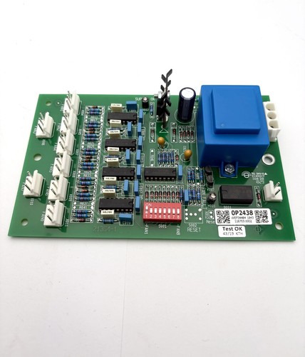
The GUTOR 0P2438 is a Fan Controller PCB Board used in GUTOR industrial UPS and power-control equipment. The referenced board is identified with 21364-1, matching product records for the GUTOR OP2438 fan-control PCB.
This board is designed to work as part of the cooling and thermal-management section of a GUTOR system. It should be installed as a system component and matched carefully with the original board number, connector arrangement, and UPS configuration.
The referenced 21364-1 identification is particularly useful when sourcing a replacement because GUTOR equipment contains several generations of control and interface boards with similar physical construction.
📊 Product Datasheet
| Parameter | Specification |
|---|---|
| Brand | GUTOR |
| Model | 0P2438 |
| Series | GUTOR UPS / Power System |
| Product Name | Fan Controller PCB Board |
| Part Number | 21364-1 |
| Board Type | Fan Control / Cooling Controller PCB |
| Application | UPS Cooling and Thermal Management |
| System Function | Fan Monitoring and Control |
| Product Status | Legacy / Maintenance Spare |
| Manufacturer | GUTOR |
| Power Supply | System-dependent |
| Operating Voltage | System-dependent |
| Communication | System-dependent |
| Dimensions | Configuration-dependent |
| Weight | Configuration-dependent |
⚠️ Exact electrical ratings, fan output specifications, dimensions, and connector pin assignments should be verified against the original board and the applicable GUTOR equipment documentation. The 0P2438 / 21364-1 identification should be used as the primary replacement reference.
⚙️ Main Features
🔹 GUTOR UPS fan-control PCB
🔹 Part number 21364-1
🔹 Designed for industrial cooling-system control
🔹 Supports fan-related control functions within the UPS system
🔹 Used as a system-level replacement PCB
🔹 Suitable for maintenance of legacy GUTOR equipment
🔹 Compact electronic control-board construction
🔹 Intended to work with the associated GUTOR power-control architecture
🛠️ Operating Procedure & How to Use
The 0P2438 should not be operated as an independent general-purpose fan controller unless the original GUTOR documentation specifically permits standalone testing.
Before installation:
- Confirm the original board is marked 0P2438.
- Verify 21364-1 against the replacement.
- Photograph all existing connectors and wiring.
- Record the original board position.
- Check connectors for corrosion, looseness, or physical damage.
- Shut down the associated GUTOR UPS/system.
- Isolate all applicable AC and DC power sources.
- Verify that hazardous voltage has been removed.
- Use appropriate ESD protection.
- Install the board in the original position.
- Reconnect all wiring exactly as documented.
- Check associated cooling fans for mechanical blockage.
- Restore power according to the equipment procedure.
- Check fan operation and system alarms.
- Verify normal UPS operation.
🔌 Startup Sequence
⚠️ GUTOR UPS equipment can contain hazardous AC and DC energy. Installation should be performed by qualified personnel.
- Confirm the 0P2438 is correctly installed.
- Check all connectors and wiring.
- Verify associated fan assemblies are correctly connected.
- Confirm cabinet ventilation is unobstructed.
- Restore control power according to the GUTOR procedure.
- Allow the control system to initialize.
- Check the fan-controller status.
- Confirm that the cooling fans start as required.
- Monitor fan operation and abnormal-temperature alarms.
- Verify communication with the associated UPS control system.
- Check the UPS operating status.
- Perform the required functional test before returning the equipment to service.
⏹️ Shutdown Sequence
- Place the UPS in the approved safe operating state.
- Follow the normal GUTOR shutdown procedure.
- Isolate the relevant AC supply.
- Isolate the DC/battery source where required.
- Verify the absence of hazardous voltage.
- Allow internal components to discharge according to the equipment procedure.
- Remove the fan controller PCB only after complete isolation.
- Protect the removed board against ESD and mechanical damage.
Do not disconnect the fan-controller PCB from an energized UPS unless the specific GUTOR service documentation explicitly permits live maintenance.
📖 Product Usage Notes
The main purpose of the 0P2438 is associated with fan and cooling control. In a UPS system, adequate cooling is essential because power semiconductors, transformers, rectifiers, inverters, and other internal components can generate significant heat.
When replacing the board, check more than just the PCB number:
🔍 0P2438 model number
🔍 21364-1 part number
🔍 Board revision
🔍 Connector layout
🔍 Cable positions
🔍 Fan quantity
🔍 Fan supply voltage
🔍 Original UPS model
🔍 Alarm configuration
🔍 Board mounting position
A replacement board should match the original hardware configuration. Do not modify fan wiring or substitute a different fan voltage without confirming the system design.
🔧 Maintenance Recommendations
Regularly inspect the cooling system together with the controller board.
🧹 Keep cabinet air passages clean.
🌀 Check that cooling fans rotate freely.
🔌 Inspect fan connectors and wiring.
🌡️ Check for abnormal temperature alarms.
⚡ Verify that the fan supply is within the approved system range.
🔍 Inspect the PCB for burnt components, discoloration, corrosion, or damaged connectors.
If a replacement 0P2438 is installed but the fans still do not operate, check the fans, wiring, upstream power supply, fuses, and temperature/control signals before assuming that the replacement PCB is defective.
❓ Common Questions & Answers
Q: What is the GUTOR 0P2438?
A: It is a GUTOR Fan Controller PCB Board used in an industrial UPS/power-control system.
Q: What is the part number?
A: The referenced board is identified as 21364-1.
Q: What is the main function of this board?
A: It is associated with cooling-fan control and monitoring within the GUTOR system.
Q: Is 0P2438 a complete UPS controller?
A: No. It is a dedicated fan-control PCB and operates as part of the larger GUTOR control architecture.
Q: Can I test the board by connecting an ordinary fan?
A: This should not be assumed. The board’s fan outputs, control signals, protection circuits, and supply requirements are system-specific.
Q: Can another GUTOR fan board replace 0P2438?
A: Not automatically. The part number, revision, fan voltage, connector configuration, and UPS model should all match.
Q: What should I check before purchasing?
A: Check 0P2438, 21364-1, board revision, connector arrangement, original UPS model, and physical condition.
Q: What happens if the fan controller fails?
A: Cooling fans may fail to operate correctly, potentially causing increased internal temperature and triggering thermal alarms or UPS protection functions.
Q: Can the PCB be hot-swapped?
A: Do not assume that it can. Power isolation is recommended unless the specific GUTOR service procedure explicitly supports live replacement.
Q: Is the board suitable for general industrial fan control?
A: It is designed for GUTOR equipment. It should not be treated as a universal fan controller without verified electrical documentation.
🔎 Recommended GUTOR Related Models & Modules
- GUTOR 0P2438 | 21364-1 — Fan Controller PCB
- GUTOR 0P2446 | 640-1017 — Main Processor Board
- GUTOR 0P2447 | 640-1017 — Main Processor Board
- GUTOR 0P9910 | 0021404 — Interface Fuse Board
- GUTOR 0P0360 — UPS Controller PCB
- GUTOR 0P0363 — Signal Controller
- GUTOR 0P0280 — AC Power Supply Module
- GUTOR 0P0284 — DC Power Supply Module
- GUTOR 0P9914 — Adapter / Interface Board
- GUTOR 0P9917 — Interface / Control Board