Description
📌 Product Introduction
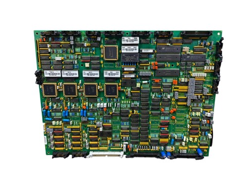
The GUTOR 0P2446 / 640-1017 is a Main Processor Board used in GUTOR power and UPS control equipment. Available product records identify 0P2446 as a GUTOR Main Processor Card / Main Control CPU Board, with the board identification 640-1017.
The board is associated with GUTOR UPS control and monitoring systems and functions as a central processing/control component rather than as a general-purpose PLC. A related technical listing identifies 0P2446 as a PCB controller for XXW 3PH/1PH UPS equipment, with reference designator A070.
Because 640-1017 also appears with closely related GUTOR processor-board configurations, the complete model number 0P2446, revision, connectors, and UPS system configuration should be checked before replacement.
📊 Product Datasheet
| Parameter | Specification |
|---|---|
| Brand | GUTOR by Schneider Electric |
| Model | 0P2446 |
| Series | GUTOR UPS / Power Control System |
| Product Name | Main Processor Board |
| Part Number | 640-1017 |
| Board Type | Main Processor / Control CPU PCB |
| Reference Designator | A070 |
| Application | UPS Control and Monitoring |
| System Compatibility | GUTOR 3-Phase / 1-Phase UPS Systems |
| Product Status | Legacy / Maintenance Spare |
| Processor Function | Main System Control |
| PWM Reference | 2 kHz, system-dependent |
| Dimensions | Configuration-dependent |
| Weight | Approx. 2.0 kg |
| Power | System-dependent |
The approximately 2.0 kg weight is reported by a product record for the 0P2446 Main Control CPU Board.
⚠️ Exact input voltage, power consumption, dimensions, processor specification, I/O configuration, and firmware should be confirmed from the individual board and the associated GUTOR UPS documentation. Some third-party technical listings provide additional electrical information, but these specifications should not be treated as universal for every 0P2446 installation.
⚙️ Main Features
🔹 GUTOR Main Processor / Control CPU Board
🔹 Part number 640-1017
🔹 Designed for GUTOR UPS control systems
🔹 Supports system control and monitoring functions
🔹 Associated with 3-phase and 1-phase UPS equipment
🔹 System-level processing and control
🔹 Suitable for legacy UPS maintenance and replacement
🔹 Compact PCB assembly for installation within the GUTOR control architecture
🛠️ Operating Procedure & How to Use
The 0P2446 is a system-specific processor board. It should be installed only in compatible GUTOR equipment and should not be operated as an independent PLC.
Before installation:
- Confirm the complete identification: 0P2446 / 640-1017.
- Compare the replacement board with the original unit.
- Check the board revision and component layout.
- Photograph all cables and connectors before removing the original board.
- Record the original board position.
- Record the UPS model and system configuration.
- Shut down the UPS using the approved operating procedure.
- Isolate AC and DC power sources.
- Verify that hazardous voltage has been removed.
- Use ESD protection when handling the PCB.
- Inspect connectors and mounting hardware.
- Install the processor board in its designated position.
- Reconnect all cables carefully.
- Restore power according to the GUTOR startup procedure.
- Check diagnostics, alarms, communication, and UPS operating status.
🔌 Startup Sequence
⚠️ GUTOR UPS equipment can contain hazardous AC and DC energy. Installation and commissioning should be performed by qualified personnel.
- Confirm the UPS is in a safe condition.
- Verify that the processor board is correctly seated.
- Check all ribbon cables and connectors.
- Confirm control-power connections.
- Verify grounding.
- Restore control power according to the UPS procedure.
- Allow the processor system to initialize.
- Check board/system status indications.
- Check active alarms.
- Verify communication with associated control and interface boards.
- Check rectifier, inverter, static-switch, and monitoring functions as applicable.
- Confirm normal UPS status.
- Perform the required functional test before returning the system to service.
⏹️ Shutdown Sequence
- Transfer the UPS/load to the approved operating condition.
- Follow the normal GUTOR shutdown procedure.
- Stop the associated inverter or power-conversion functions as required.
- Isolate AC and DC sources.
- Verify absence of hazardous voltage.
- Allow stored energy to discharge according to the equipment procedure.
- Remove the processor board only after complete isolation.
- Place the removed PCB in an ESD-safe package.
Never remove the 0P2446 from an energized UPS simply because the front panel indicates that the system is stopped.
📖 Product Usage Notes
When replacing this processor board, physical compatibility is only one consideration. The board works as part of a larger GUTOR control architecture, so the UPS model, connected interface boards, control configuration, firmware, and wiring must also be considered.
Before removing the existing board, record:
🔍 Model number
🔍 Part number
🔍 Revision
🔍 UPS model
🔍 Board position
🔍 Connector arrangement
🔍 Firmware/software information
🔍 Existing configuration
The 0P2446 is specifically identified as a main processor card, while the 640-1017 designation is also seen in related GUTOR processor-board records. Always use the complete identification when purchasing a replacement.
The referenced market listing for this model identifies the board as a used component, while another current listing describes a 0P2446 unit with damaged connector clips and minor handling scratches. Condition should therefore be verified on the actual unit before installation.
❓ Common Questions & Answers
Q: What is the GUTOR 0P2446?
A: It is a GUTOR Main Processor Board / Main Processor Card identified by part number 640-1017.
Q: What is the main function of 0P2446?
A: It serves as a central processor/control board within the associated GUTOR UPS and power-control system.
Q: Is 0P2446 a PLC?
A: No. It is a dedicated GUTOR UPS control processor board rather than a general-purpose PLC.
Q: What is the reference designator?
A: A technical product record identifies the 0P2446 as reference designator A070.
Q: What UPS systems can use this board?
A: Available records associate it with GUTOR 3-phase and 1-phase UPS equipment. The exact compatibility depends on the complete UPS model and system configuration.
Q: What is the part number?
A: The board is identified as 640-1017, with 0P2446 as the GUTOR model/part identifier.
Q: Is 0P2446 interchangeable with 0P2447?
A: Do not assume so. Both appear in the same general 640-1017 processor-board family, but their model identifiers are different. The original UPS configuration and complete board markings must be checked before substitution.
Q: What is the approximate weight?
A: One product record lists approximately 2.0 kg for the 0P2446 Main Control CPU Board.
Q: Can the board be hot-swapped?
A: Do not assume that it can. Power isolation should normally be completed before removing or installing a processor PCB unless the specific GUTOR documentation explicitly permits hot-swapping.
Q: What should I check before purchasing?
A: Confirm 0P2446, 640-1017, revision, connector arrangement, UPS model, board position, and system configuration.
🔎 Recommended GUTOR / Schneider Electric Related Models
- GUTOR 0P2447 / 640-1017 — Main Processor Board
- GUTOR 0P2446 / 640-1017 — Main Processor Board
- GUTOR 0P2405 — Interface Fuse / FC UPS Component
- GUTOR PXP Series — UPS Systems
- GUTOR Modular UPS — Modular Power Protection Systems
- GUTOR VX Series — UPS Systems
- GUTOR SDC Series — DC UPS / Power Systems
- GUTOR Main Control CPU Boards — UPS Control Electronics
- GUTOR UPS Interface Boards — Control and Signal Interface
- Schneider Electric GUTOR UPS Control Modules — Related Power-Control Hardware
The related 0P2447 and 0P2446 boards are particularly relevant when sourcing GUTOR processor-board spares, but matching the exact model and revision remains essential before substitution.