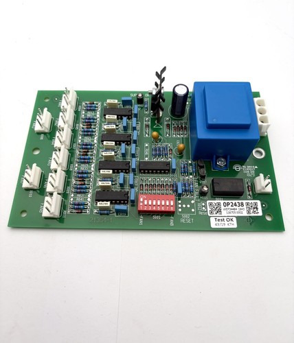


Description
The GUTOR 0P2556B is an Interface Card / PCB Assembly identified by part number 640-2556B. GUTOR product catalogs identify 0P2556B as an Interface Board, while other industrial listings identify the assembly as a PSU Relay PCB and show Rev 04 on the board.
The board is intended for integration into GUTOR industrial UPS and power-conversion equipment. It is a system-specific interface component and should be matched with the original equipment configuration before replacement.
📊 Product Datasheet
| Parameter | Specification |
|---|---|
| Brand | GUTOR |
| Model | 0P2556B |
| Series | GUTOR UPS / Power System |
| Product Name | Interface Card / Interface Board |
| Part Number | 640-2556B |
| Board Type | Interface PCB / PSU Relay PCB |
| Revision | Rev 04 |
| Application | UPS Power Supply / Interface System |
| Manufacturer | GUTOR |
| Product Status | Legacy / Maintenance Spare |
| Controller Platform | Interface Board |
| Electrical Rating | System-dependent |
| Power Supply | System-dependent |
| Dimensions | Configuration-dependent |
| Weight | Configuration-dependent |
| Country of Origin | Switzerland is listed for a matching 0P2556B / 640-2556B unit. |
The exact voltage, relay ratings, connector pinout, dimensions, and power consumption should be verified against the actual board and the associated GUTOR system documentation. Available records specifically identify 0P2556B as an interface board and a matching 640-2556B Rev 04 unit as a PSU relay PCB.
⚙️ Main Features
🔹 GUTOR interface PCB assembly
🔹 Model 0P2556B
🔹 Part number 640-2556B
🔹 Rev 04 version available
🔹 Associated with PSU relay/interface functions
🔹 Designed for GUTOR industrial UPS equipment
🔹 Suitable for legacy system maintenance
🔹 System-specific connector and control interface
🛠️ Operating Procedure & How to Use
The 0P2556B should be installed as part of the compatible GUTOR power system. It should not be treated as a universal relay board.
Before installation:
- Confirm the board marking 0P2556B.
- Verify 640-2556B.
- Check the board revision.
- Compare the PCB layout with the original.
- Photograph all connectors and wiring.
- Record the original board location.
- Identify the associated GUTOR UPS model.
- Shut down the system according to the approved procedure.
- Isolate all relevant AC and DC power sources.
- Verify that hazardous voltage has been removed.
- Use ESD protection when handling the PCB.
- Install the board in the original position.
- Reconnect all cables and terminals correctly.
- Check relay and interface wiring.
- Restore power according to the GUTOR startup procedure.
- Check system alarms and interface functions.
🔌 Startup Sequence
⚠️ GUTOR UPS equipment may contain hazardous AC/DC energy. Installation and commissioning should be performed by qualified personnel.
- Confirm the PCB is correctly installed.
- Verify all connectors are seated.
- Check relay/interface wiring.
- Confirm grounding and cabinet connections.
- Restore control power according to the system procedure.
- Allow the controller to initialize.
- Check system status indications.
- Verify communication with associated control boards.
- Check active alarms.
- Verify the PSU/interface functions.
- Check relay operation where applicable.
- Monitor the UPS during controlled operation.
- Return the system to normal service after functional verification.
⏹️ Shutdown Sequence
- Place the UPS in the approved safe operating condition.
- Follow the normal GUTOR shutdown procedure.
- Isolate the applicable AC supply.
- Isolate DC/battery power where required.
- Apply lockout/tagout procedures.
- Verify absence of hazardous voltage.
- Allow stored energy to discharge.
- Confirm safe voltage levels with appropriate test equipment.
- Disconnect the interface PCB.
- Remove and package the board using ESD protection.
Do not remove the 0P2556B from an energized system unless the specific GUTOR service documentation explicitly permits live replacement.
📖 Product Usage Notes
The 0P2556B is identified in GUTOR catalogs as an interface board. A matching industrial listing further describes 640-2556B Rev 04 as a PSU Relay PCB, indicating that the board can be involved in relay/interface functions associated with the power-supply section.
When replacing the board, check:
🔍 Model number
🔍 Part number
🔍 Revision
🔍 Connector arrangement
🔍 Relay configuration
🔍 Original UPS model
🔍 Board position
🔍 Wiring arrangement
🔍 Associated power-supply modules
🔍 System configuration
Do not assume that another GUTOR interface board is interchangeable simply because it has a similar connector layout.
🔧 Maintenance Recommendations
🧹 Keep the PCB and cabinet free of dust and conductive contamination.
🔌 Inspect connectors for oxidation or loose contacts.
⚡ Check relay terminals for overheating or discoloration.
🔍 Inspect the PCB for damaged components or cracked solder joints.
🌡️ Check for abnormal heat around relay and power-interface components.
📋 Record the exact board identification before replacement.
If a replacement board produces an unexpected alarm, check the associated power supply, relay wiring, communication connections, and controller configuration before concluding that the interface PCB is defective.
❓ Common Questions & Answers
Q: What is the GUTOR 0P2556B?
A: It is a GUTOR Interface Card / PCB Assembly identified by part number 640-2556B.
Q: What is the part number?
A: The associated part number is 640-2556B.
Q: What revision is available?
A: A matching industrial listing identifies the board as Rev 04.
Q: Is it a PSU relay board?
A: A matching 640-2556B Rev 04 listing describes it as a PSU Relay PCB, while GUTOR catalogs classify 0P2556B as an interface board.
Q: Is 0P2556B a standalone relay controller?
A: No. It is designed as part of the GUTOR power-system architecture.
Q: Can I power it directly on a workbench?
A: This is not recommended without the correct GUTOR test procedure because the board’s supply and relay/interface connections are system-dependent.
Q: Can another GUTOR interface board replace it?
A: Not automatically. Part number, revision, connector configuration, relay functions, and system compatibility must be verified.
Q: What should I check before ordering?
A: Confirm 0P2556B, 640-2556B, revision, board layout, connector positions, and the original GUTOR equipment model.
Q: Can the board be hot-swapped?
A: Do not assume that it can. Normal replacement should be performed after proper system shutdown and electrical isolation unless the OEM procedure explicitly permits live replacement.
Q: Where is this type of board used?
A: It is associated with GUTOR industrial UPS and power-system equipment, particularly interface/power-supply circuitry.
🔎 Recommended GUTOR Related Models & Modules
- GUTOR 0P2556B / 640-2556B — Interface Board
- GUTOR 0P2552 / 640-2552 — Power Connection Board
- GUTOR 0P2553A — External Connection PCB
- GUTOR 0P2558A — Parallel Connection PCB
- GUTOR 0P2560A — Static Switch Controller PCB
- GUTOR 0P6257 / 21430-3 — SDC Control Unit Card
- GUTOR 0P6267 — PCB / ISODRIVER Board
- GUTOR 0P9912A — Relay Board
- GUTOR 0P0010AB — Fan Speed Control Board
- GUTOR 0P2438 / 21364-1 — Fan Controller PCB