Description
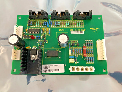
The GUTOR 0P6205 is identified as a Crowbar component used in Gutor industrial power-system equipment. A Gutor spare-parts reference specifically lists 0P6205 as a 250–500 VDC Crowbar.
A crowbar circuit is a protective device designed to respond to an abnormal overvoltage condition by creating a controlled low-impedance path, allowing upstream protection to disconnect the affected circuit. In a Gutor system, this type of board is used as part of the DC power protection architecture.
The supplied product is described as a Gutor PCB Card / Extension Board Crowbar. Because detailed public documentation for this exact PCB is limited, installation should be based on the original Gutor system drawings and the identification markings on the physical board.
📋 Product Datasheet
| Parameter | Specification |
|---|---|
| Brand | GUTOR Electronics |
| Model | 0P6205 |
| Series | GUTOR Industrial Power System |
| Product Name | Extension Board Crowbar |
| Product Type | PCB Protection Board |
| Function | DC Overvoltage / Crowbar Protection |
| Rated Voltage Range | 250–500 VDC |
| Application | GUTOR Power / UPS Systems |
| Product Status | Legacy / Replacement Spare |
| Board Construction | Industrial Printed Circuit Board |
The 250–500 VDC crowbar rating is specifically listed in a Gutor spare-parts reference for 0P6205.
⚠️ Exact dimensions, weight, input/output terminals, trigger threshold, semiconductor specifications, and connector pinout should be verified from the original board or Gutor technical documentation rather than estimated.
🔧 Operating Standards & How to Use
The 0P6205 should only be installed in the Gutor equipment for which the board was originally designed.
🔹 Verify the complete 0P6205 identification before installation.
🔹 Confirm that the system DC voltage falls within the applicable 250–500 VDC range.
🔹 Inspect the PCB for cracked components, burned areas, damaged terminals, or corrosion.
🔹 Compare the connector arrangement with the existing board.
🔹 Use ESD protection when handling the PCB.
🔹 Verify polarity and wiring before energizing the system.
🔹 Make sure all upstream protection devices are correctly installed.
🔹 Do not bypass the crowbar protection circuit during commissioning.
⚠️ A crowbar is a protective circuit. An incorrect installation can cause a high-current fault when the protection circuit activates.
▶️ Startup Sequence
- 🔍 Confirm the GUTOR 0P6205 part number.
- 🧰 Inspect the PCB and connectors.
- 🔌 Verify all wiring and polarity.
- 🛡️ Check associated fuses and protective devices.
- ⚡ Energize the system according to the Gutor equipment procedure.
- 📊 Monitor the DC bus voltage.
- 🔎 Check for abnormal alarms or protection indications.
- 🧪 Verify normal system operation under controlled conditions.
- 📈 Monitor voltage stability before returning the equipment to service.
⏹️ Shutdown Sequence
- Stop the associated equipment using its normal shutdown procedure.
- Isolate the relevant AC/DC power sources.
- Apply lockout/tagout procedures.
- Verify that the DC bus is no longer energized.
- Measure the circuit to confirm safe voltage levels.
- Allow stored energy to dissipate according to the equipment procedure.
- Only then remove or replace the 0P6205 PCB.
⚠️ High-voltage DC systems can retain dangerous stored energy after the main supply has been switched off. Do not rely only on indicator lights to determine that the circuit is safe.
📘 Product Usage Instructions
The 0P6205 is not a conventional power-supply or control PCB. Its purpose is associated with crowbar protection of a DC power circuit.
A simplified protection arrangement can be understood as:
DC Power System → 0P6205 Crowbar Protection → System Load
Under normal operating conditions, the protection circuit remains inactive. If the applicable abnormal-voltage condition occurs, the crowbar circuit is intended to force the associated protection system to disconnect the affected power source.
The Gutor spare-parts reference specifies the 0P6205 for 250–500 VDC crowbar applications.
For replacement, do not modify the trigger circuit, semiconductor components, jumpers, or PCB wiring unless the original Gutor service documentation specifically authorizes the modification.
🛠️ Installation & Maintenance
🔹 Keep the PCB clean and dry.
🔹 Use an antistatic bag for storage.
🔹 Avoid touching component leads and connector contacts.
🔹 Inspect high-voltage components for discoloration or cracking.
🔹 Check PCB traces for signs of overheating.
🔹 Inspect connectors for oxidation.
🔹 Check associated fuses and protection components.
🔹 Verify DC voltage before returning the system to service.
🔹 Record the PCB part number and revision during replacement.
🔹 Perform a controlled functional test after installation.
❓ Common Questions & Answers
Q: What is the GUTOR 0P6205?
A: It is identified as a Crowbar protection component/PCB used in Gutor industrial power equipment. The Gutor spare-parts reference specifies it for 250–500 VDC applications.
Q: What voltage range is associated with 0P6205?
A: The available Gutor spare-parts reference lists 250–500 VDC.
Q: What is a crowbar circuit?
A: It is an overvoltage protection method that intentionally creates a low-impedance fault path when an abnormal voltage condition is detected, allowing upstream protection to disconnect the circuit.
Q: Is 0P6205 a power supply?
A: No. It is a protection board/crowbar component rather than a conventional AC/DC or DC/DC power supply.
Q: Is it a PLC module?
A: No. The 0P6205 is a dedicated protection PCB for Gutor power equipment.
Q: Can it be tested with a normal multimeter?
A: Basic continuity and visual checks may be possible, but a complete crowbar functional test requires appropriate high-voltage test equipment and procedures. Do not apply test voltage casually.
Q: Can another Gutor PCB replace 0P6205?
A: Not automatically. The voltage range, circuit topology, connector configuration, mounting arrangement, and protection characteristics must match.
Q: Can I install this board while the UPS is powered?
A: It should not be hot-swapped unless the specific Gutor system documentation explicitly states that live replacement is permitted.
Q: What should I check before purchasing?
A: Confirm the complete GUTOR 0P6205 identification, PCB layout, connector configuration, mounting arrangement, physical condition, and intended system application.
Q: Is 0P6205 suitable for a 600 VDC system?
A: The available Gutor spare-parts reference specifies 250–500 VDC. Therefore, it should not be assumed suitable for 600 VDC applications.
⭐ Recommended GUTOR Related Series & Models
- GUTOR 0P6205 — Crowbar Extension Board
- GUTOR SILCON 21108-2 — Voltage Supply
- GUTOR 0500129 — Auxiliary PSU Assembly
- GUTOR SILCON — Industrial UPS Series
- GUTOR SILCON DP — UPS Series
- GUTOR PEW — Industrial UPS Series
- GUTOR PDW — Industrial UPS Series
- GUTOR 0400207 — Control Unit Reference
- GUTOR OM-94035B — Front Panel Interface
- GUTOR Industrial Power Protection Boards — Related legacy protection assemblies
⚠️ These are related Gutor products and references, not confirmed direct replacements for 0P6205. The exact electrical and mechanical specifications must be matched before substitution.
📦 Replacement Identification
For purchasing and maintenance records, use the complete identification:
GUTOR | 0P6205 | EXTENSION BOARD | CROWBAR | 250–500 VDC
For a surplus replacement, it is recommended to verify the PCB markings, connector condition, component condition, mounting holes, and available electrical test information before installation.