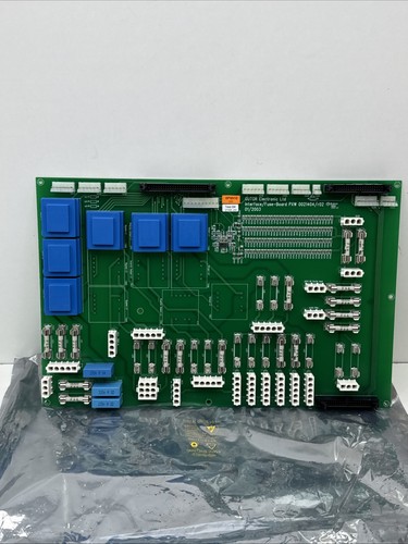


Description
📌 Product Introduction
The GUTOR 0P9910 is an Interface Fuse Board used in GUTOR UPS power systems. Available industrial spare-parts records identify it as an Interface Card / PCA Interface Fuse UPS, DP 220 VDC, with the internal system designation A071.
The referenced identification also includes PXW 0021404 / R02 / 01/2003, indicating a specific PXW assembly and revision/date marking. Related GUTOR system documentation identifies the 0P9910 as an INTERFACE FUSE UPS 220 VDC, W.O. T1..12, item A071, used within GUTOR PEW UPS equipment.
This is a system-specific interface/protection board rather than a standalone controller. It is particularly relevant when maintaining older GUTOR UPS installations where the original interface board must be replaced without redesigning the complete system.

📊 Product Datasheet
| Parameter | Specification |
|---|---|
| Brand | GUTOR |
| Model | 0P9910 |
| Series | GUTOR PXW / PEW UPS System |
| Product Name | Interface Fuse Board |
| Board Type | PCA Interface / Fuse Board |
| Internal Designation | A071 |
| System | PXW UPS / GUTOR UPS |
| DC System Rating | 220 VDC |
| Assembly Identification | 0021404 |
| Revision | R02 |
| Date Marking | 01/2003 |
| Application | UPS Interface and DC Fuse Protection |
| Product Status | Legacy / Maintenance Spare |
| Power | System-dependent |
| Dimensions | Configuration-dependent |
| Weight | Configuration-dependent |
The 220 VDC application and A071 designation are supported by multiple industrial spare-parts records.
A GUTOR system parts listing specifically identifies 0P9910 as the INTERFACE FUSE UPS 220 VDC, W.O.T1..12, while another catalog describes it as an interface card for a Fuse UPS, DP 220 VDC, A071.
⚙️ Main Functions
🔹 Interface board for GUTOR UPS equipment
🔹 DC fuse/interface distribution
🔹 Designed for 220 VDC UPS systems
🔹 Internal system designation A071
🔹 PXW-related GUTOR control/power architecture
🔹 Interfaces associated UPS circuits through dedicated fuse paths
🔹 Supports maintenance of legacy GUTOR UPS installations
The reference to W.O. T1..12 in a GUTOR system parts list indicates that the board is associated with multiple protected/interface paths rather than serving simply as a general signal PCB.
🛠️ Operating Procedure & How to Use
The 0P9910 is intended to operate as part of a GUTOR UPS system. It should not be powered or tested as an independent general-purpose circuit board.
Before installation:
- Confirm the complete board identification 0P9910.
- Verify the A071 system designation.
- Check the PXW assembly identification.
- Confirm the 0021404 / R02 / 01/2003 markings where applicable.
- Compare fuse positions and ratings with the original board.
- Record all connected cables and terminals.
- Shut down the UPS according to the approved procedure.
- Isolate AC and DC sources.
- Verify that the 220 VDC bus is de-energized.
- Check for stored energy before touching the board.
- Use suitable electrical and ESD protection.
- Install the replacement board in the correct position.
- Restore all connections according to the original wiring.
- Verify fuse installation and ratings.
- Restore power following the approved GUTOR startup sequence.
- Check alarms, DC distribution, and UPS status.
⚠️ A 220 VDC UPS system can present a serious electrical hazard. Fuse-board replacement should be performed only by qualified personnel following the applicable electrical safety procedure.
🔌 Startup Sequence
- Confirm the UPS is in a safe and controlled state.
- Verify the 0P9910 is correctly installed.
- Check all terminal and connector connections.
- Verify that every fuse position has the correct specified fuse.
- Confirm there are no short circuits or wiring errors.
- Check grounding and cabinet connections.
- Energize the control system according to the GUTOR procedure.
- Energize the appropriate DC section.
- Monitor DC voltage and current.
- Check fuse-board/interface status.
- Verify communication with the associated control boards.
- Check UPS alarms and status indications.
- Confirm normal rectifier, battery, inverter, and output operation as applicable.
- Perform the required functional test.
⏹️ Shutdown Sequence
- Place the UPS/load in the approved safe operating state.
- Follow the normal GUTOR shutdown procedure.
- Isolate the AC input as required.
- Isolate the DC/battery source.
- Verify that the 220 VDC bus has been safely isolated.
- Allow stored energy to discharge according to the equipment procedure.
- Verify absence of hazardous voltage with appropriate test equipment.
- Only then remove the 0P9910 board.
- Protect the removed board and fuses against accidental contact and contamination.
Do not remove or replace fuses on an energized 220 VDC circuit unless the specific equipment procedure and rated maintenance method explicitly allow it.
📖 Product Usage Notes
The 0P9910 is best understood as an interface and fuse board within the GUTOR UPS architecture. A related GUTOR parts list identifies A071 as the interface board, alongside A070 for the PCB controller, A072 for the signal controller, A201 for the AC power supply, and A202 for the DC power supply.
When replacing the board, record the original fuse arrangement carefully. Do not substitute fuse ratings simply because a different value physically fits the holder.
For legacy GUTOR equipment, it is useful to document:
🔍 0P9910 part number
🔍 A071 designation
🔍 PXW system model
🔍 Fuse positions
🔍 Fuse ratings
🔍 Terminal wiring
🔍 Board revision
🔍 Assembly number
🔍 DC bus voltage
🔍 Associated controller board
The 0P9910 has also appeared in a public procurement catalog as a TCI Interface, N/P 0P9910, demonstrating continued maintenance demand for this legacy GUTOR component.
❓ Common Questions & Answers
Q: What is the GUTOR 0P9910?
A: It is a GUTOR Interface Fuse Board / PCA Interface board used in UPS equipment.
Q: What is the internal designation?
A: The board is identified as A071 in GUTOR system parts records.
Q: What voltage system is it associated with?
A: Available GUTOR parts records identify it as an interface fuse board for a 220 VDC UPS system.
Q: What does PXW refer to?
A: PXW is part of the GUTOR equipment/system identification used for associated UPS power-control hardware. The exact PXW configuration should be confirmed from the equipment nameplate and system documentation.
Q: Is the 0P9910 a controller?
A: No. It is primarily an interface/fuse board. GUTOR parts records separately identify the A070 PCB controller, while A071 is the interface board.
Q: What does “W.O. T1..12” mean?
A: A GUTOR system parts listing describes the board as an interface fuse UPS 220 VDC W.O. T1..12, indicating its association with multiple protected/interface paths.
Q: What is 0021404 / R02 / 01/2003?
A: These markings identify the referenced PXW assembly, revision, and date information. They should be retained when matching a replacement board.
Q: Can another GUTOR fuse board replace 0P9910?
A: Not automatically. The DC voltage, fuse arrangement, connector configuration, board revision, and UPS system must match.
Q: Can I replace a fuse with a higher-rated fuse?
A: No. The fuse rating must follow the approved GUTOR system documentation. Increasing the fuse rating can remove intended circuit protection.
Q: What should I check before purchasing?
A: Confirm 0P9910, A071, the PXW system, 220 VDC rating, assembly identification, revision, fuse arrangement, and connector layout.
🔎 Recommended GUTOR Related Models & Modules
- GUTOR 0P9910 A071 — Interface Fuse Board
- GUTOR 0P9909 — Related Interface Fuse Board
- GUTOR 0P0360 A070 — UPS/DP Controller PCB
- GUTOR 0P0363 A072 — Signal Controller
- GUTOR 0P0280 A201 — AC Supply Module
- GUTOR 0P0284 A202 — DC Power Supply
- GUTOR 0P9914 — Adapter Board
- GUTOR 0P9917 — Interface / Control Board
- GUTOR 353-9002 — Controller Memory
- GUTOR 640-0610 — Interface Fuse Board
These related parts appear in GUTOR spare-parts catalogs and system component lists. They are useful references when sourcing parts for the same generation of GUTOR UPS equipment, but they should not be treated as automatic replacements for 0P9910.