

Description
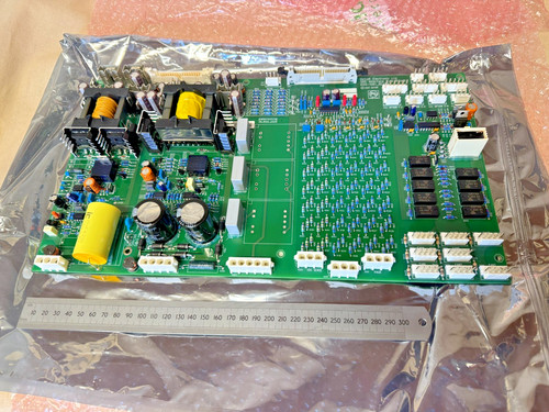
The GUTOR 21.457-6 is a GUTOR printed circuit board identified with the additional markings E193317 and 328DC. It is intended as a system-specific PCB for GUTOR industrial power and UPS equipment.
Because reliable public technical documentation for this exact board is limited, the safest product description is to identify it as a Printed Circuit Board (PCB) rather than assigning an unverified function such as rectifier, controller, communication interface, or power supply.
For replacement applications, the complete identification on the physical board should be matched, including 21.457-6, E193317, and 328DC.
📋 Product Datasheet
| Parameter | Specification |
|---|---|
| Brand | GUTOR Electronics |
| Model | 21.457-6 |
| Series | GUTOR Industrial UPS / Power Systems |
| Product Name | Printed Circuit Board |
| PCB Identification | E193317 |
| Additional Marking | 328DC |
| Product Type | Industrial PCB / Electronic Board |
| Application | GUTOR Power / UPS Equipment |
| Product Status | Legacy / Replacement Spare |
| Condition | Used / Surplus — verify actual unit |
⚠️ Exact electrical function, input/output voltage, power rating, dimensions, weight, connector configuration, and circuit function are not sufficiently documented in reliable public sources for this exact PCB. These specifications should be confirmed from the physical board and the customer’s GUTOR equipment documentation rather than estimated.
🔧 Operating Standards & How to Use
🔹 Confirm all board markings before installation.
🔹 Match 21.457-6, E193317, and 328DC with the existing PCB.
🔹 Verify the host GUTOR UPS or power-system model.
🔹 Compare connector locations and mounting points.
🔹 Photograph the original wiring before removal.
🔹 Record jumper, DIP-switch, or configuration settings if present.
🔹 Use an ESD wrist strap when handling the PCB.
🔹 Inspect the board for corrosion, cracked components, or overheating.
🔹 Verify every cable connection before energizing the system.
🔹 Do not apply external power to the PCB unless the correct test procedure is known.
▶️ Startup Sequence
- 🔍 Verify the PCB identification and revision markings.
- 🧰 Inspect the board and connectors.
- 🔌 Confirm all wiring against the original installation.
- 🛡️ Verify grounding and cabinet safety.
- ⚡ Restore system power according to the applicable GUTOR procedure.
- 💡 Check UPS/system status indications.
- 🖥️ Check the controller or display for alarms.
- 📊 Verify the functions associated with the PCB.
- 🔄 Monitor system operation for abnormal indications.
- 🧪 Perform a controlled functional test before returning the equipment to normal service.
⏹️ Shutdown Sequence
- Place the GUTOR system in the approved maintenance or bypass state.
- Follow the normal UPS shutdown procedure.
- Isolate applicable AC/DC power sources.
- Apply lockout/tagout procedures where required.
- Verify that hazardous voltage has been removed.
- Allow stored energy to discharge according to the equipment procedure.
- Disconnect PCB wiring.
- Remove the board using ESD precautions.
- Install the replacement PCB.
- Restore power and perform a complete functional check.
⚠️ GUTOR UPS systems can contain hazardous AC/DC voltage and stored energy. PCB replacement should be performed by qualified personnel following the equipment-specific maintenance procedure.
📘 Product Usage Instructions
The 21.457-6 should be treated as a GUTOR system-specific PCB.
A typical replacement workflow is:
GUTOR UPS / Power System → Existing PCB → Record Identification & Wiring → Replace 21.457-6 → Restore Power → Functional Test
Before removing the original board, record:
🔹 Part number: 21.457-6
🔹 Board marking: E193317
🔹 Additional marking: 328DC
🔹 Board location
🔹 Connector positions
🔹 Cable assignments
🔹 Jumper/DIP-switch configuration
🔹 PCB revision information
After installation, check system startup, alarms, control functions, and any equipment functions associated with the board.
Since the exact circuit function of this PCB is not confirmed by reliable public documentation, it should not be marketed as a rectifier, inverter board, communication board, or power-supply board unless the physical PCB or GUTOR documentation confirms that function.
🛠️ Installation & Maintenance
🔹 Keep the PCB clean and dry.
🔹 Use an antistatic bag for storage.
🔹 Avoid touching IC pins and connector contacts.
🔹 Check connectors for oxidation or mechanical damage.
🔹 Inspect components for overheating.
🔹 Check PCB traces for burns or discoloration.
🔹 Inspect capacitors for swelling or leakage.
🔹 Verify mounting hardware and spacers.
🔹 Maintain the original cable routing.
🔹 Record the replacement PCB identification in maintenance records.
❓ Common Questions & Answers
Q: What is GUTOR 21.457-6?
A: It is a GUTOR printed circuit board identified by part number 21.457-6.
Q: What other markings are associated with the board?
A: The supplied identification includes E193317 and 328DC.
Q: What is the exact function of this PCB?
A: Reliable public information available for this exact part is insufficient to establish its specific circuit function. It is therefore safest to identify it as a GUTOR PCB rather than assign an unverified function.
Q: Is it a rectifier board?
A: This cannot be confirmed from the available identification alone.
Q: Is it a communication interface?
A: This cannot be confirmed from the available identification alone.
Q: Is it a power-supply board?
A: This cannot be confirmed without the applicable GUTOR system documentation or physical PCB information.
Q: Can it be installed in any GUTOR UPS?
A: No. Compatibility depends on the specific GUTOR equipment, PCB position, connectors, electrical characteristics, and system configuration.
Q: Can another GUTOR PCB replace it?
A: Not automatically. A replacement should be confirmed by complete part number and system compatibility.
Q: Can the board be hot-swapped?
A: Do not assume that it can. Power should normally be isolated before PCB replacement unless the specific GUTOR equipment documentation explicitly permits live replacement.
Q: What should I check before purchasing?
A: Confirm 21.457-6, E193317, 328DC, physical PCB layout, connectors, mounting points, condition, and compatibility with the customer’s GUTOR equipment.
Q: Why are all PCB markings important?
A: Legacy industrial equipment can have visually similar boards with different electrical functions or revisions. Matching all available markings reduces the risk of installing an incompatible board.
⭐ Recommended GUTOR Related Series & Models
- GUTOR 21.457-6 — Printed Circuit Board
- GUTOR 0C0949 — PXW Rectifier Module
- GUTOR 0P0530-A076 — Communication Interface
- GUTOR UNC1X-0P-00089 — SDC Interface / PSU
- GUTOR 0P0282 — 400 VDC PSU PCB
- GUTOR 0P0284 — DC Power Supply PCB
- GUTOR 0P0363 — Signalling / Control Board
- GUTOR 0P9912A — Relay Board
- GUTOR 0P2420 — Network Management Card
- GUTOR SILCON Series — Industrial UPS Systems
These are related GUTOR products and are not confirmed direct replacements for 21.457-6.