

Description
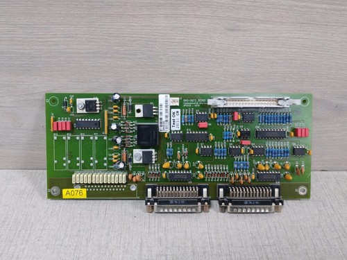
The GUTOR P61473A is an OEM PCB assembly identified by 21382-2 and 640-4049A. Available industrial parts records identify 640-4049A Rev. 2 as a GUTOR controller board associated with the 0P0360 designation.
The supplied listing identifies the item as a GUTOR OEM PCB assembly, making the complete identification important when selecting a replacement. The 21382-2 PCB number is also listed separately as a GUTOR printed circuit board.
Because GUTOR UPS and static-converter systems use application-specific control and interface boards, the complete board number, revision, connectors, and host-system configuration should be matched before installation.
📋 Product Datasheet
| Parameter | Value |
|---|---|
| Brand | GUTOR |
| Model | P61473A |
| Series | GUTOR UPS / Static Converter |
| Product Name | OEM PCB Assembly / Controller Board |
| PCB Part Number | 21382-2 |
| GUTOR Part Number | 640-4049A |
| Revision | Rev. 02* |
| Board Type | Controller / Control PCB |
| Application | Industrial UPS / Power Conversion |
| Condition | OEM / Surplus |
| Country of Origin | Switzerland |
| Power Supply | System-dependent |
| Communication | System-dependent |
| Mounting | Internal PCB Assembly |
- Current market records identify 640-4049A Rev. 2 with GUTOR 0P0360, while the supplied listing title specifies 21382-2 and 640-4049A. Confirm the actual revision printed on the physical board before installation.
⚙️ Operating Guidelines
🔹 Verify P61473A / 21382-2 / 640-4049A against the original board.
🔹 Check the revision marking before replacement.
🔹 Inspect PCB connectors, terminals, components, solder joints, and mounting points.
🔹 Confirm the host GUTOR UPS or static-converter model.
🔹 Use ESD protection when handling the PCB.
🔹 Do not remove or install the board while the associated power system is energized unless the manufacturer’s service documentation specifically allows live replacement.
🔹 Verify all wiring before restoring power.
🛠️ How to Use
- 🔍 Record all identification numbers from the original PCB.
- ⚡ Shut down the associated GUTOR system.
- 🔌 Isolate AC and DC/battery power sources.
- 🔒 Apply the required lockout/tagout procedure.
- ⏳ Allow internal capacitors and DC buses to discharge.
- 🧤 Use ESD protection.
- 🧩 Remove the existing PCB carefully.
- 🔧 Install the P61473A board in the correct rack or mounting position.
- 🔗 Reconnect all cables and connectors according to the original configuration.
- 🔍 Inspect the installation before energizing.
- ⚡ Restore power using the GUTOR system startup procedure.
- 🚨 Check alarms and diagnostic indications.
- ✅ Verify normal UPS/control operation.
🔌 Power-On Sequence
- 🔍 Inspect the PCB and connectors.
- 🧰 Confirm correct mounting and wiring.
- 🔋 Restore the approved auxiliary/DC supply.
- ⚡ Restore the main system power according to the GUTOR procedure.
- ⏳ Allow the control system to initialize.
- 🖥️ Check controller status.
- 🚨 Check for PCB, communication, or system alarms.
- 📊 Verify system readings.
- ✅ Return the UPS/static converter to normal operating mode.
⛔ Power-Off Sequence
- Notify the responsible operator.
- Place the connected equipment in a safe condition.
- Shut down the GUTOR system normally.
- Isolate AC input.
- Isolate battery/DC sources.
- Apply lockout/tagout.
- Wait for the specified discharge period.
- Verify absence of hazardous voltage.
- Remove the PCB only after the system has been confirmed de-energized.
⚠️ GUTOR UPS equipment can contain hazardous stored electrical energy. PCB replacement should be performed by qualified service personnel.
📘 Product Usage Notes
The 640-4049A identification is associated in industrial parts records with a GUTOR controller board and 0P0360.
The separate 21382-2 designation is also documented as a GUTOR PCB. This makes P61473A + 21382-2 + 640-4049A the preferred identification combination for purchasing and replacement.
Do not assume that another GUTOR PCB with a similar appearance is interchangeable. GUTOR boards can perform different control, interface, power, or monitoring functions even when they are physically similar.
❓ Common Questions & Answers
Q: What is the GUTOR P61473A?
A: It is an OEM GUTOR PCB assembly identified with 21382-2 and 640-4049A.
Q: What is the PCB number?
A: The PCB is identified as 21382-2.
Q: What is the GUTOR part number?
A: The supplied unit is identified as 640-4049A.
Q: Is 640-4049A a controller board?
A: Available industrial parts records identify 640-4049A Rev. 2 as a GUTOR controller board associated with 0P0360.
Q: What system is it used in?
A: It is associated with GUTOR industrial UPS and power-conversion equipment.
Q: Is this a programmable PLC module?
A: It should not be treated as a general-purpose PLC module. It is a GUTOR system-specific PCB.
Q: Can 21382-2 replace another GUTOR controller board?
A: Not automatically. The complete part number, revision, connectors, firmware/configuration, and host system must match.
Q: What should I check before purchasing?
A: Check P61473A, 21382-2, 640-4049A, revision marking, PCB layout, connectors, and the original GUTOR equipment model.
Q: Does the board require programming?
A: The exact configuration requirements depend on the host GUTOR system. Do not assume that a replacement PCB is automatically plug-and-play.
Q: Where is GUTOR associated with manufacturing?
A: GUTOR is historically associated with Switzerland, but the exact country marking of an individual PCB should be verified from its physical label.
Q: What is the safest replacement method?
A: Photograph and document the original wiring, isolate all energy sources, verify the exact PCB identification, install the matching board, and perform a controlled functional test.
⭐ Recommended Other GUTOR Models / Parts
- GUTOR 0P0360 — Controller Board
- GUTOR 640-4049A Rev. 02 — Controller Board
- GUTOR 21382-2 — PCB Assembly
- GUTOR 0P2552 — Power Connection Board
- GUTOR 640-2552 — Power Connection Board
- GUTOR 0P2447 — Main Processor Board
- GUTOR 640-1017 — Main Processor Board
- GUTOR 21108-2 — Voltage Supply Board
- GUTOR 0P2405A — Interface Fuse Board
- GUTOR 640-0717 — Interface Fuse Board