
Description
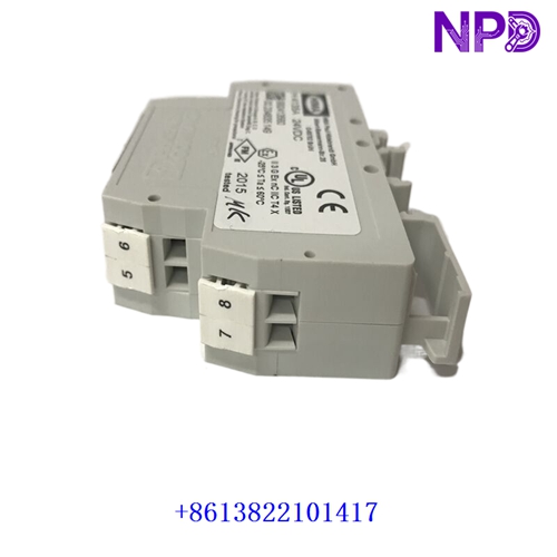
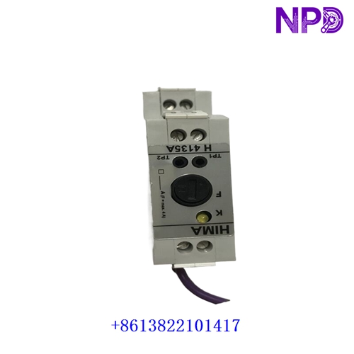
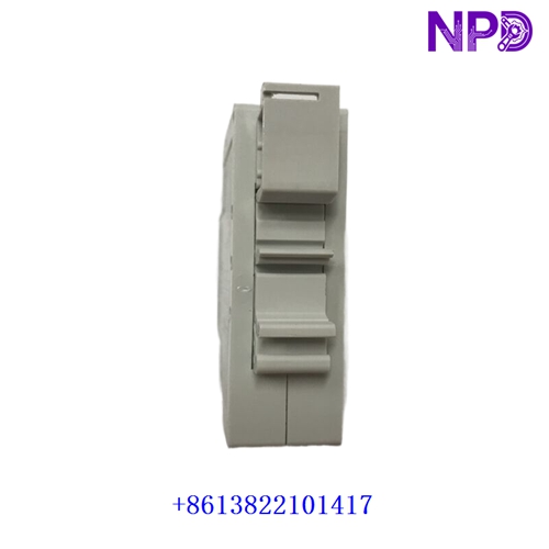
The HIMA H4135A (Part / Drawing Number: 992413560) is a high-reliability, safety-related relay module enclosed in a compact electronic housing. Designed by HIMA for critical industrial automation environments, it is engineered for safety instrumented systems and emergency shutdown loops up to SIL 3 (Safety Integrity Level 3) in accordance with IEC 61508. The module utilizes diverse internal relay configurations to securely switch safety-critical circuits, such as shutting down fuel supplies in combustion plants.
| Parameter | Specification |
| Brand / Manufacturer | HIMA (Paul Hildebrandt GmbH + Co KG) |
| Model / Type | H4135A Safety-Related Relay Module |
| Part / Stock Number | 992413560 |
| Safety Integrity Level | Up to SIL 3 (per IEC 61508 / IEC 61511 / EN 50156-1) |
| Nominal Operating Voltage | 24 V DC (-15% to +20%), current consumption approx. 40 mA (floating input) |
| Contact Output Type | Normally Open (NO) relay contact with internal diversity configuration |
| Switching Voltage / Current | Max. 250 VAC / 220 VDC; Switching current from 10 mA up to 4 A |
| Switching Times | Switching time approx. 8 ms; Reset time approx. 6 ms |
| Enclosure & Mounting | IP 20 protection rating (housing), mounts on standard 35 mm DIN rail or C-profile |
| Operating Temperature | -25°C to +60°C |
| Product Status | Industrial Safety Automation Spare Part |
First-Run Inspection Checklist
- ☑ Physical & Housing Integrity
Inspect the electronic module housing, front labeling, connection terminals, and locking latches for any transit damage or mechanical distortion.
- ☑ DIN Rail Seating & Alignment
Ensure that the 35 mm DIN rail or C-profile is securely mounted, clean, and free of metallic debris before snapping the module into place.
- ☑ Power & Fuse Verification
Confirm that incoming 24 V DC power rails and external fusing limits (max 4 A slow-blow / T-fuse on terminal 8 monitoring circuits) match safety loop specifications prior to energization.
Routine Maintenance & Servicing
- 🛠 Proof-Test Interval (SIL Compliance)
For SIL 3 applications, perform a mandatory functional proof test at least every 5 years (every 20 years for SIL 2). This test requires verifying that each series-connected relay contact opens properly in the de-energized state using a continuity tester.
- 🔌 Terminal & Wiring Tightness
Periodically inspect screw or spring terminal blocks to guarantee secure wire insertion (up to 2.5 mm^2 / AWG 14) and prevent vibration-induced loosening.
Troubleshooting & Common Issues
- ⚠️ Failure to Open / Contact Sticking
If routine diagnostic or proof tests indicate continuity across contacts while the module is de-energized, immediately replace the unit to preserve safety integrity loop requirements.
- ⚠️ Input Power Faults
If the internal relay fails to actuate, verify that the 24 V DC control input is within the -15% to +20% tolerance band and check upstream safety PLC output channels.
Safety Precautions
- 🔐 Qualified Personnel Only
Installation, wiring, proof-testing, and module replacement must be performed exclusively by certified technicians trained in functional safety management and safety-instrumented systems.
- ⚠️ Hazardous Area (Zone 2) Conditions
If mounted in a Zone 2 explosive atmosphere, the module must be enclosed in an approved cabinet achieving at least IP 54 protection (meeting EN 60079-15) and serviced only when de-energized.
Frequently Asked Questions (Q&A)
- ❓ Q1: What is the primary function of the HIMA H4135A module?
A: It functions as a safety-related switching relay that provides galvanic isolation and reliable execution of safety shutdown commands (up to SIL 3) for critical industrial actuators and burner controls.
- ❓ Q2: How is the safety architecture achieved inside the module?
A: The unit uses redundant relays configured in diversity (series connections) to ensure that a single component failure will not compromise the safety-related de-energization function.