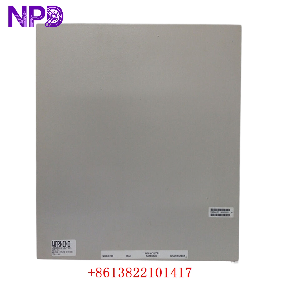

Description
The HONEYWELL SIEGER 05701-A-0361 is a specialized engineering control card designed for the 5701 gas detection series. This module provides advanced signal processing and interface capabilities for industrial safety systems. Engineered for high reliability in mission-critical environments, it facilitates precise management of sensor data and communication within the gas detection rack, ensuring rapid response to atmospheric hazards.

Technical Specifications
| Parameter | Description |
| Model | 05701-A-0361 |
| Manufacturer | HONEYWELL SIEGER |
| Dimensions | Standard Eurocard Format |
| Weight | Approximately 0.35 kg |
| Origin | United Kingdom |
| Application | Gas Detection System Control |
Operational Guidelines & Usage
🔹 Startup Sequence
- Ensure the card is firmly inserted into the designated slot in the 5701 rack system.
- Confirm that all rear-plane connections and field wiring are secured correctly.
- Power on the main control rack.
- Allow the card to perform its internal boot-up and self-diagnostics.
- Verify that the system registers the card in the control loop; check for normal status indicators (Green LEDs).
🔹 Shutdown Sequence
- Inform control room operations that the specific channel/module will be offline.
- Switch the unit into “Inhibit” or “Maintenance” mode via the central controller to prevent accidental alarm triggering.
- Power down the system rack or remove the card carefully from the chassis.
- Place the card in a clean, dry, and anti-static environment for storage.
🔹 Normal Operational Flow
- The module continuously monitors the input signal from the connected gas sensor.
- The internal circuitry processes the raw data, converting it into calibrated gas concentration values.
- The system compares inputs against programmed alarm thresholds.
- Output signals (relays and digital feedback) are managed in real-time based on the concentration data.
🔹 Parameter Configuration
- Enter the configuration menu via the system’s management interface.
- Use the designated engineering software or hardware jumpers/switches on the card (as per the specific model configuration) to set alarm points and signal scaling.
- Calibrate the zero and span settings to match the field sensor characteristics.
- Confirm all changes and save the configuration to the non-volatile memory of the card.
🔹 Mode Switching
- Monitoring Mode: The operational state where the card reports real-time data and manages alarms.
- Service/Inhibit Mode: Used during maintenance. Requires manual selection via the controller interface to bypass alarm logic while leaving the card powered.
Common Questions & Answers (Q&A)
💡 Q: How can I resolve a communication error on this card?
A: Check the card’s seating in the rack to ensure pins are making full contact. Verify that the backplane connector is free of dust or oxidation. If the issue persists, test the card in a known-good slot.
💡 Q: Is this card compatible with all 5701 series sensors?
A: The 05701-A-0361 is designed for specific sensor interfaces. Always verify the part number against your system’s technical manual to ensure compatibility with your existing gas sensor technology.
💡 Q: What is the significance of the “Maintenance” light?
A: This light indicates that the module is in an inhibited state. It serves as a safety reminder that the module is currently not reporting alarms to the site’s emergency shutdown system.
💡 Q: What should I do if the card fails to retain calibration data?
A: This may indicate an issue with the onboard backup battery or non-volatile memory. If settings revert after a power cycle, the card may require professional repair or replacement.