
Description
🌐 Product Overview
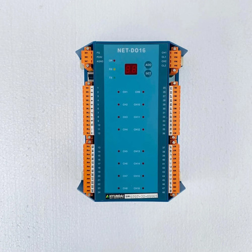
The Hyundai NET-DO16 is a high-density digital output module designed for seamless integration within Hyundai’s proprietary distributed control systems (DCS) and programmable logic controller (PLC) networks. Featuring 16 independent, optically isolated channels, this module is engineered to safely drive field actuators, solenoid valves, interposing relays, and status indicators. With its robust noise immunity and rapid switching response, the NET-DO16 ensures precise automation control and long-term hardware reliability in demanding industrial and marine control environments.
⚙️ Technical Specifications
- Series: NET Automation I/O Series
- Dimensions: 145mm x 40mm x 115mm
- Weight: 0.35 kg
- Origin: South Korea
- Output Configuration: 16 Channels (Source or Sink depending on wiring topology)
- Rated Voltage: 24V DC nominal (15V to 30V DC operational range)
- Isolation Rating: Optocoupler isolation rated at 1500V AC between field logic and internal backplane
- Output Current Capacity: Max 0.5A per channel (with internal short-circuit protection)
🚀 Application Fields
- Actuator Control: Driving pneumatic and hydraulic solenoid valves across manufacturing assembly lines.
- Motor Control Centers (MCC): Operating coil currents for heavy-duty interposing relays and magnetic contactors.
- Marine Automation: Managing alarm signaling lights and status indicator matrices within engine control rooms (ECR).
- Process Infrastructure: Coordinating valve manifolds and dosing pump triggers in water treatment and chemical processing plants.
📖 Product Instructions
- Module Insertion: Align the NET-DO16 module with the designated slot on the system backplane rack. Push firmly until the top and bottom extraction latches click into place, ensuring a secure connection to the communication bus.
- Field Wiring: Connect the external 24V DC load supply to the specified power common pins on the terminal block. Route individual channel outputs directly to the positive terminal of each field device.
- Address Configuration: Set the module node identification or slot number via the front-facing rotary switches (if applicable) or map the I/O address table directly within the system’s central programming environment.
✅ Initial Startup Checklist
- Verify that the external 24V DC load power supply is stable, within tolerance, and properly fused.
- Confirm that the terminal block connector is fully seated and clamped tight against the module faceplate.
- Power up the rack chassis and verify that the module’s “RUN” or “HEALTHY” LED lights up a steady green.
- Force individual channels through the software control panel to test that corresponding channel-status LEDs illuminate and the physical field devices actuate correctly.
🛠️ Maintenance & Care
- Terminal Inspection: Conduct annual checks to ensure terminal screws remain tight and free from oxidation caused by humid or salty marine environments.
- Backplane Contact Cleaning: During scheduled system overhauls, blow out accumulated dust from the backplane connectors using clean, dry compressed air.
- Component Monitoring: Periodically check the diagnostic log files of the central controller for any transient overcurrent or short-circuit faults flagged by the module.
⚠️ Safety Precautions
- Load Limits: Do not exceed the maximum current capacity of 0.5A per channel. For loads exceeding this threshold, always utilize an external interposing relay.
- Isolate Power: Turn off the external load power supply before removing or connecting the field terminal block to prevent accidental short circuits or pin arcing.
- Electrostatic Discharge: Keep the module inside its anti-static packaging until installation, and handle it only by the plastic enclosure edges to protect internal surface-mount components.
🔍 Troubleshooting & FAQ
- Q: A specific channel LED is on, but the physical field device is not responding. What is the cause?
- A: This indicates that the internal logic side is working, but the field circuit is broken. Check the external 24V DC loop power supply, verify that the field device coil isn’t open-circuited, and check for loose terminal block connections.
- Q: The module “ERR” (Error) LED is flashing a distinct pattern, and all outputs have dropped offline.
- A: A flashing error light typically points to a backplane communication fault or an overtemperature trip caused by an overloaded channel. Disconnect the terminal block to see if the fault clears; if it does, check your field loads for short circuits.
- Q: Does this module support hot-swapping while the central processor is actively running?
- A: Hot-swapping parameters depend on the specific generation of the primary backplane rack chassis. Refer to your system infrastructure manual to confirm if live insertion is supported before removing the module during an active process.