Description
🔧 Product Overview
The ICS TRIPLEX T8312-4 is a Trusted TMR Expander Interface Adapter Unit designed for use in the Trusted Triple Modular Redundant safety system.
The T8312-4 provides the physical and electrical connection between Trusted Expander Interface Modules installed in the Controller Chassis and up to four downstream Expander Chassis. It is therefore an important chassis interconnection component rather than a conventional PLC CPU or I/O module.
The T8312 family is available in different versions. The T8312-4 supports up to four Expander Chassis, while the T8312-7 version supports up to seven. The suffix is therefore an important part of the replacement identification.
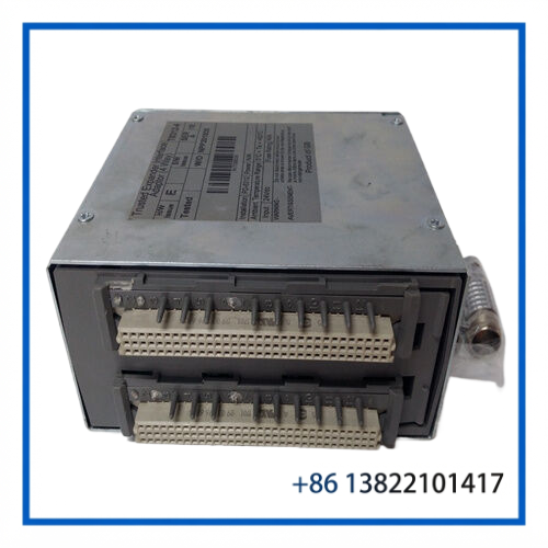
The unit includes a PCB assembly inside a shielded metal enclosure and uses locking connectors to provide reliable interconnection within the Trusted system architecture. It clips onto the rear connectors of the Trusted Controller Chassis.
⚙️ Key Features
🔹 Trusted Triple Modular Redundant system component
🔹 Model T8312-4
🔹 Expander Interface Adapter Unit
🔹 Supports up to four Expander Chassis
🔹 Provides Controller-to-Expander Chassis interconnection
🔹 Four 12-pin ODU connector interfaces
🔹 96-way Type C internal connector
🔹 Shielded metal enclosure for EMC performance
🔹 Locking connector design
🔹 Designed for rear mounting on the Trusted Controller Chassis
🔹 Supports the Trusted Expander Interface architecture
🔹 250 Mbps Expander Bus data rate
📋 Product Datasheet
| Parameter | Specification |
|---|---|
| Brand | ICS TRIPLEX |
| Model | T8312-4 |
| Series | Trusted |
| Product Name | Trusted TMR Expander Interface Adapter Unit |
| Product Type | Chassis Interface Adapter |
| System Architecture | Triple Modular Redundant (TMR) |
| Main Function | Controller-to-Expander Chassis Interconnection |
| Expander Chassis Capacity | Up to 4 |
| Related Chassis | T8100 Controller Chassis |
| Related Interface Module | T8311 Trusted TMR Expander Interface |
| Expander Bus Data Rate | 250 Mbps |
| External Connectors | 4 × 12-pin ODU Connectors |
| Internal Connector | 96-way Type C Connector |
| Construction | PCB in Shielded Metal Enclosure |
| Mounting Position | Rear of Trusted Controller Chassis |
| Dimensions | Approx. 130 × 60 × 115 mm |
| Weight | Approx. 0.65 kg |
| Operating Temperature | -5°C to +60°C |
| Operating Humidity | 5–95% RH, Non-Condensing |
| Vibration | 10–57 Hz ±0.075 mm / 57–150 Hz 1.0 g |
| Shock Resistance | 15 g, Half-Sine Wave, 11 ms |
| Application | Trusted Safety and Control Systems |
| Country of Origin | Verify from Product Nameplate |
| Condition | Verify Actual Item Condition |
The published T8312 specification identifies a 250 Mbps Expander Bus data rate, 130 × 60 × 115 mm dimensions, approximately 0.65 kg weight, and the stated environmental limits.
🔄 Operating Function
The T8312-4 acts as an interface path between the Controller Chassis and connected Expander Chassis.
A simplified system structure is:
Trusted Controller Chassis → T8311 Expander Interface Module → T8312-4 Adapter Unit → Interface Cable → Expander Chassis
The adapter itself is not a processor and does not perform normal PLC I/O processing. Its primary role is to provide the physical and electrical interconnection required for communication between the Trusted Expander Interface Modules and the downstream Expander Chassis architecture.
The T8312-4 configuration is intended for Trusted systems requiring connections to a maximum of four Expander Chassis. Larger configurations may use the T8312-7 version instead.
🛠️ Installation and Replacement
Before replacing the unit, confirm the complete system configuration.
Recommended checks include:
- Confirm the exact part number T8312-4.
- Verify that the installation requires the four-chassis version.
- Check the Trusted Controller Chassis model.
- Confirm the installed T8311 Expander Interface Module configuration.
- Inspect all rear chassis connectors.
- Check the condition of the 12-pin ODU connectors.
- Inspect interface cables for mechanical damage.
- Confirm the Expander Chassis identification and configuration.
- Check connector locking before commissioning.
- Verify system diagnostics after installation.
The T8312 assembly clips onto the rear connector arrangement of the Controller Chassis. Mechanical alignment is important because damaged or incorrectly seated connectors can interrupt communication with connected Expander Chassis.
🔍 Maintenance Tips
🧹 Keep the connector area clean and free from dust or conductive contamination.
🔌 Inspect the 12-pin connectors for bent pins, corrosion, or mechanical wear.
🛡️ Check the metal enclosure and shielding arrangement during maintenance.
🔧 Verify that all locking connectors are securely engaged.
📡 Investigate interface cables when an Expander Chassis communication problem occurs.
⚡ Do not treat the T8312-4 as a conventional active I/O module during troubleshooting. The associated T8311 interface modules, cables, and Expander Chassis should also be checked.
📦 Store spare units in protective packaging and avoid mechanical stress on the connectors.
For safety-critical applications, replacement and system testing should follow the site’s approved safety-system maintenance procedure.
❓ Frequently Asked Questions
Q: What is the ICS TRIPLEX T8312-4?
A: It is a Trusted TMR Expander Interface Adapter Unit used to connect Trusted Controller Chassis Expander Interface Modules with downstream Expander Chassis.
Q: How many Expander Chassis can the T8312-4 support?
A: The T8312-4 version supports connections to up to four Expander Chassis.
Q: What is the difference between T8312-4 and T8312-7?
A: The T8312-4 supports up to four Expander Chassis, while the T8312-7 supports up to seven.
Q: Is the T8312-4 a PLC processor?
A: No. It is an interface adapter unit and does not replace a Trusted processor module.
Q: Is the T8312-4 an I/O module?
A: No. It is a chassis interconnection component used within the Trusted Expander Interface architecture.
Q: What modules work with the T8312?
A: It is associated with the Trusted T8311 Expander Interface Modules installed in the Controller Chassis.
Q: What is the Expander Bus data rate?
A: The published specification identifies a 250 Mbps Expander Bus data rate.
Q: Can T8312-7 replace T8312-4 directly?
A: It should not be substituted automatically. The correct version should be selected according to the existing system configuration and required number of Expander Chassis.
Q: What should be checked before purchasing a replacement?
A: Confirm the exact T8312 variant, number of connected Expander Chassis, T8311 interface configuration, Controller Chassis type, connector condition, and installed cable arrangement.
🔄 Recommended ICS TRIPLEX Models
- ICS TRIPLEX T8312-4 – Trusted TMR Expander Interface Adapter Unit
- ICS TRIPLEX T8312-7 – Seven-Chassis Expander Interface Adapter
- ICS TRIPLEX T8311 – Trusted TMR Expander Interface Module
- ICS TRIPLEX T8310 – Trusted TMR Expander Processor
- ICS TRIPLEX T8300 – Trusted Expander Chassis
- ICS TRIPLEX T8100 – Trusted TMR Controller Chassis
- ICS TRIPLEX T8110B – Trusted TMR Main Processor
- ICS TRIPLEX T8121 – Trusted Processor Interface Adapter
- ICS TRIPLEX T8314 – Trusted Fibre Optic TX/RX Unit
- ICS TRIPLEX T8153 – Trusted Communication Interface Adapter
These products belong to the Trusted safety and control architecture. Compatibility depends on the complete chassis, processor, interface, cable, and system configuration.
🏭 Application Summary
The ICS TRIPLEX T8312-4 is a system-specific Trusted TMR Expander Interface Adapter Unit used for connecting a Trusted Controller Chassis to up to four Expander Chassis.
Its role is primarily interconnection rather than control processing. For this reason, a communication fault affecting multiple remote chassis may involve the T8312-4, associated T8311 Expander Interface Modules, interface cables, or the Expander Chassis hardware.
For replacement and spare-parts management, the most important identification point is the complete suffix T8312-4. The four-chassis configuration must not be confused with the T8312-7 version. Always verify the installed Trusted system architecture, number of connected chassis, connector condition, and interface configuration before installation.