
Description
🌐 Product Overview
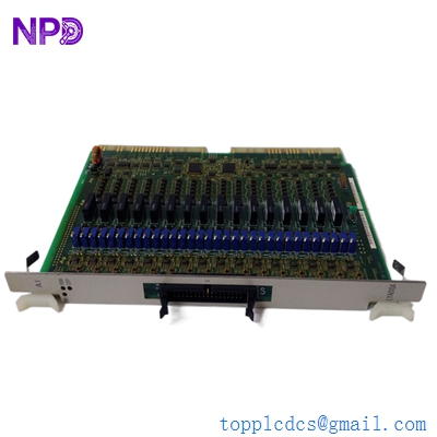
The Kongsberg 65801811 is a high-precision, marine-grade DC motor drive printed circuit board (PCB) specifically designed for Kongsberg X-Band maritime radar systems. This board serves as the primary speed and positioning controller for the radar’s turning unit antenna array. Engineered to maintain a constant rotational speed under extreme wind loads and harsh open-ocean conditions, the 65801811 ensures precise azimuth timing signals and stable target synchronization for the ship’s navigation and tracking display systems.
⚙️ Technical Specifications
- Series: Maritime Radar Turning Unit Control Components
- Dimensions: 190mm x 155mm x 32mm
- Weight: 0.58 kg
- Origin: Norway
- Application Voltage: 24V DC to 48V DC drive rails
- Output Type: Pulse Width Modulation (PWM) regulated DC motor output
- Feedback Loops: Integrated optocoupler / encoder inputs for real-time speed monitoring
- Interface Ports: Specialized multi-pin ribbon connectors for power distribution and system data telemetry

🚀 Application Fields
- Commercial Navigation Radars: Speed regulation for X-band scanner units installed on cargo vessels, tankers, and passenger cruise lines.
- Offshore Surveillance Systems: Antenna drive control for sea-surface monitoring networks on drilling platforms and FPSO units.
- Coast Guard & Naval Craft: High-reliability tactical radar positioning systems operating in demanding weather environments.
- Vessel Traffic Services (VTS): Land-based harbor radar rotation infrastructure demanding continuous, 24/7 mechanical operation.
📖 Product Instructions
- Board Assembly: Ensure the radar transceiver housing is completely isolated from all power grid sources. Slide the 65801811 PCB into its dedicated card cage slots within the turning unit housing, lining up the grounding tracks carefully.
- Harness Connections: Plug the motor power output leads and transceiver data ribbon cables into their matching on-board sockets until the physical locking mechanisms click into place.
- Static Shielding: Re-attach all localized internal RF shielding covers over the board to prevent electromagnetic interference from the high-power radar magnetron or solid-state transmitter.
✅ Initial Startup Checklist
- Verify that the physical antenna array is completely clear of personnel, cranes, or safety netting before energizing the drive system.
- Check that all wire harnesses are routed tightly clear of the main mechanical gears and turning shafts inside the pedestal enclosure.
- Power up the radar processor and confirm that the driver board’s onboard green heartbeat indicator flashes a normal operational pattern.
- Initiate a low-power scanner test rotation to verify the antenna hits the standard rated RPM target (typically 24 RPM or 48 RPM depending on configuration) without stuttering.
🛠️ Maintenance & Care
- Carbon Dust Mitigation: Inspect the board surface every six months for traces of conductive carbon dust shed by the mechanical DC motor brushes. Clean safely using anti-static compressed air.
- Contact Review: Check the multi-pin edge headers for surface oxidation caused by salty or humid marine environments, applying a thin layer of specialized marine contact preservative if necessary.
- Capacitor Safety Checks: Visually review the large electrolytic power filtering capacitors on the drive rails for any signs of top bulging or fluid leakage.
⚠️ Safety Precautions
- Radiation Hazard: Never activate the motor drive or rotate the antenna while maintenance personnel are working anywhere near the horizontal plane of the radar scanner array due to RF radiation hazards.
- Residual Energy: Wait at least 5 minutes after disconnecting power before touching the card to allow the internal high-voltage motor capacitors to discharge completely through their bleed resistors.
- ESD Warning: Always wear a grounded electrostatic discharge (ESD) wrist strap when handling the drive card to avoid piercing the sensitive high-speed logic gates with static electricity.
🔍 Troubleshooting & FAQ
- Q: The radar unit displays an “Antenna Rotation Error” or azimuth fault on the bridge bridge screen.
- A: This indicates the drive board is not detecting velocity feedback from the turning unit. Check for a broken motor brush, a mechanical obstruction blocking the array, or a misaligned optical encoder plugged into the board.
- Q: The rotation speed drops significantly when the vessel sails through high winds.
- A: Check the voltage levels arriving at the drive rail inputs on the board. If the power feed drops under heavy load, it indicates an issue with the upstream power supply card or excessive mechanical drag in the pedestal bearings.
- Q: Can this drive board be tested on a standard workbench safely without the antenna attached?
- A: Bench testing is possible but requires a matched dummy resistive load connected to the motor terminals. Running the PWM circuit completely open-circuit for extended periods during troubleshooting can cause erroneous fault loops or trigger voltage spikes.