
Description
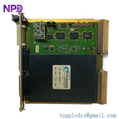
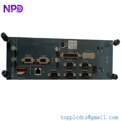
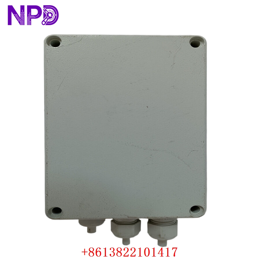
The KONGSBERG 8100289 (often referred to as an RPME module) is a precision-engineered electronics component utilized within the Kongsberg Maritime control architecture. This module is primarily tasked with high-speed signal processing and data acquisition, acting as an essential interface for rotating machinery monitoring and speed regulation. It is designed to ensure maximum uptime in demanding marine environments by providing reliable I/O handling and seamless communication between field sensors and the central control system.

⚙️ Technical Specifications
- Dimensions: 240 mm x 150 mm x 80 mm
- Weight: 0.95 kg
- Country of Origin: Norway
- Power Input: 24V DC (Nominal)
- Operating Temperature: -20°C to +60°C
- Housing: Conductive industrial-grade enclosure for EMI shielding
- Protection Class: IP20 (Requires installation in protected cabinet)
🏗️ Application Areas
- Propulsion Speed Monitoring
- Engine Performance Analysis
- Rotating Machinery Vibration Monitoring
- Integrated Bridge System (IBS) Sensors
- Real-time Data Logging for Marine Engines
📖 Product Usage Instructions
The RPME module should be installed on a standard DIN-rail or dedicated rack mount within a bridge-controlled or engine-room cabinet. Use shielded, twisted-pair cabling for all incoming sensor signals to maintain data integrity against high-frequency interference. Ensure that the module is properly seated and the locking mechanism is engaged to prevent disconnection due to ship vibration.
🌐 Communication Configuration Steps
- IP Address: Access the module via the Kongsberg maintenance utility. Assign a static IP address that aligns with the vessel’s internal control network configuration.
- Station Number: Configure the device station ID via the onboard DIP switches or the software configuration interface to ensure it is recognized by the master controller.
- Baud Rate: Set the communication speed to match the system bus (typically set to 500kbps or 1Mbps depending on the specific fieldbus protocol requirements).
⚡ Power-Up Debugging Flow
- Confirm the 24V DC input voltage using a multimeter to ensure there is no significant ripple.
- Check that the grounding strap is connected from the chassis to the cabinet earth bus.
- Power on the module and monitor the “Heartbeat” LED. A steady blink indicates the module is executing its internal firmware.
- If the “Error” LED flashes, verify the sensor input connections (speed pickup/analog signal).
- Use the Kongsberg interface software to check if the module shows an “Active/Online” status.
✅ Initial Run Checklist
- Perform a signal injection test on all input channels to verify that the software displays the correct sensor values.
- Verify that the threshold limits for overspeed or alarm conditions are programmed correctly for the specific machine application.
- Check the communication logs for any intermittent “CRC errors” which might indicate poor cabling quality.
- Save the full module configuration file to your maintenance laptop.
- Inspect the terminal block screws for tightness to prevent loosening over time due to operational vibrations.
❓ Frequently Asked Questions (Q&A)
Q: What is the primary role of the RPME module in a maritime system? A: Its primary role is to act as an intelligent gateway for rotating machinery, converting raw pulses or analog sensor data into digital information that the central control system can act upon.
Q: Can this module operate in high-temperature engine rooms? A: It is designed for operation up to 60°C. If your engine room exceeds this, ensure the module is installed in an actively cooled or well-ventilated enclosure.
Q: How do I handle a firmware mismatch error? A: A mismatch usually occurs when the module firmware version does not match the master controller’s expectations. Use the official Kongsberg update utility to synchronize the firmware versions.
Q: Is the 8100289 hot-swappable? A: While designed for reliability, it is standard practice to cut power to the specific backplane slot before removal to avoid potential signal noise or transient damage to the sensitive input circuits.