
Description
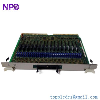
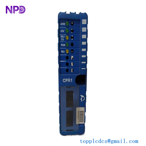
The Autronica KMH-200A (7252-084.0001) and KMJ-200 (7252-005.0003) are specialized interface and control modules historically used in Autronica’s fire detection, alarm, and control systems.
- KMH-200A (Interface Module): Typically functions as a signal processing and communication interface, facilitating the exchange of data between the fire alarm system and external equipment (such as ventilation dampers, door release systems, or emergency shutdown circuits).
- KMJ-200 (Logic/Control Module): Often serves as a localized control or relay logic board, managing specific output actions requested by the main controller based on the inputs processed by the KMH-200A.
Together, these modules form part of the modular architecture that allows Autronica systems to be highly customized for specific vessel requirements, ensuring that when an alarm is triggered, the correct automated safety responses are executed.
Key Technical Specifications
| Parameter | KMH-200A (7252-084.0001) | KMJ-200 (7252-005.0003) |
| Component Type | Communication Interface PCB | Relay/Logic Output Module |
| Compatibility | Autronica Fire Control Panels | Autronica Fire Control Panels |
| Function | Signal translation/Loop data | Relay switching/Automation control |
| Operating Voltage | 24V DC | 24V DC |
| Mounting | Cabinet Rack/DIN Rail | Cabinet Rack/DIN Rail |
| Environment | Marine-grade (IACS/MED) | Marine-grade (IACS/MED) |

Recommended Related Models
These components are often part of the same maintenance cycle for Autronica fire detection cabinets:
- 7252-008.xxxx: KMC (Control Module series)
- 7252-084.xxxx: Additional Interface board variants
- 116-BR-100: Loop Isolator Module
- 116-BWP-100: Analogue Addressable Smoke Detector
- 116-BWP-101: Analogue Addressable Heat Detector
- 116-BZ-31: Manual Call Point
- 7212-385.0009: BSA-200 (Loop Signal Processing Card)
- 7212-385.0005: BSL-300 (System Logic Board)
- 116-BW-100: Loop Controller Expansion
- 7252-010.0001: Power Supply/Battery Charger Module
Important Implementation Note: When replacing these modules, ensure that the address jumpers or software-defined addresses are correctly transferred from the faulty unit. Since these boards often handle life-safety outputs (e.g., closing fire doors), after installation, a “System Walk Test” is required to confirm that the input signal (e.g., smoke detection) correctly triggers the output action (e.g., relay activation) through the new module.