
Description
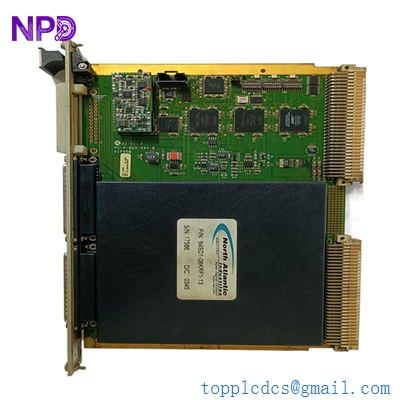
The Kongsberg KDM-8A/03-M3 is an industrial-grade, marine-certified memory and real-time clock (RTC) expansion board designed for Kongsberg’s integrated automation architectures, such as the legacy K-Chief and Albatross positioning systems. This critical module provides high-integrity volatile and non-volatile memory storage for runtime parameters, system configurations, and historical event logs. Equipped with an onboard, temperature-compensated real-time clock circuit, the KDM-8A/03-M3 ensures highly accurate, microsecond-level time-stamping for system alarms, safety interlocks, and sensor telemetry across the shipboard control network.
⚙️ Technical Specifications
- Series: KDM Control and Expansion Board Series
- Dimensions: 233mm x 160mm x 20mm (Standard Eurocard form factor)
- Weight: 0.42 kg
- Origin: Norway
- Memory Architecture: High-reliability Static RAM (SRAM) and EPROM/Flash configuration banks
- Clock Accuracy: Temperature-compensated crystal oscillator (TCXO) with less than 2ppm drift
- Backup Power Source: Onboard industrial lithium battery backup system for data and clock retention
- Bus Interface: Standardized parallel backplane interface pins for rack mounting
🚀 Application Fields
- Alarm and Event Logging: Providing precision time-stamping for centralized machinery space alarm systems.
- Dynamic Positioning (DP) Systems: Archiving configuration profiles and handling historical data backup tasks on K-Pos controller racks.
- Vessel Management Systems (VMS): Storing core control parameters for ballast, bilge, and auxiliary fuel pump automation loops.
- Marine Data Recording: Acting as the localized non-volatile memory buffer for Voyage Data Recorders (VDR) and engine room monitoring logs.
📖 Product Instructions
- Card Installation: Power down the central rack chassis completely. Align the KDM-8A/03-M3 board with the card guide rails of the designated slot, sliding it inward firmly until the DIN 41612 backplane connectors seat completely. Fasten the front panel retaining screws.
- Battery Initialization: Prior to system boot-up on a newly installed board, verify that the battery isolation jumper is set to the “ON” or “CONNECTED” position to activate the memory backup circuit.
- Time Synchronization: Once the host system boots, perform a master time synchronization sequence via the engineering workstation to align the onboard RTC with the vessel’s primary GPS master clock.
✅ Initial Startup Checklist
- Confirm that the main rack power supply is turned off before executing card insertion or extraction.
- Check that the onboard hardware configuration jumpers match the memory address mapping defined in your system architecture layout.
- Energize the system and verify that the module’s “OK” or “HEALTHY” LED lights up a steady green without triggering system bus parity error indicators.
- Extract a diagnostic status report from the host controller to verify that the memory bank is fully accessible and that the battery voltage reads within nominal limits.
🛠️ Maintenance & Care
- Battery Voltage Testing: Check the voltage of the onboard lithium backup battery annually using a digital multimeter or the system’s built-in diagnostic utility; replace the cell if the voltage falls below the critical threshold (typically 2.7V DC).
- Backplane Contact Inspections: Periodically remove the card during scheduled dry-dock periods to inspect the gold-plated backplane pins for signs of salt-crust accumulation or surface tarnishing.
- Software Database Backups: Maintain a mirror copy of the controller’s runtime parameter database on an external workstation to prevent parameter data loss when replacing legacy memory hardware.

⚠️ Safety Precautions
- Electrostatic Discharge Risk: Always utilize a grounded ESD wrist strap and an anti-static work mat when handling the board to prevent latent static damage to the sensitive memory ICs.
- Lithium Battery Warning: Do not expose the onboard lithium battery to high temperatures, open flames, or mechanical crushing, and ensure proper polarity alignment if replacing the cell.
- Strict Power Off Compliance: Never plug, unplug, or alter configuration jumpers on the KDM-8A/03-M3 board while the rack backplane is energized to avoid triggering data corruption loops or hardware shorts.
🔍 Troubleshooting & FAQ
- Q: The host controller generates a “Clock Out of Sync” or “RTC Invalidation” alarm.
- A: This message often points to an exhausted onboard lithium backup battery or an unstable crystal oscillator. Test the battery voltage first; if the battery is fully charged, verify that the system is receiving periodic NTP or GPS master clock updates.
- Q: The system fails to boot past the POST sequence and logs a “Memory Parity Error” on this slot.
- A: A parity error indicates a data corruption event in the RAM banks or a damaged memory sector on the board. Attempt a clean wipe and cold project reload; if the error recurs, the memory hardware may need servicing.
- Q: Can the backup battery be replaced while the board is plugged into the system and running?
- A: Yes, if the rack remains fully energized, the main backplane supply will keep the memory intact while you carefully swap the battery. However, it is highly recommended to perform this task offline with a full data backup to minimize risks.