
Description
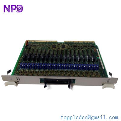
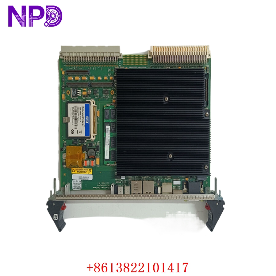
The Kongsberg Maritime ARI-12 (Part No: 8100223) is a high-reliability Analog Remote Interface module used extensively within Kongsberg’s marine automation and control systems. It acts as a specialized data acquisition node, converting physical analog signals—such as pressure, temperature, level, and flow—from field sensors into digital data streams suitable for the ship’s central control and monitoring system (CMS).
📋 Technical Specifications
🔹 Part Number: 8100223 🔹 Module Type: ARI-12 (Analog Remote Interface) 🔹 Series: Kongsberg Maritime Automation Series 🔹 Function: Analog-to-Digital Signal Conversion (A/D) 🔹 Operating Voltage: 24V DC 🔹 Weight: Approximately 0.50 kg 🔹 Origin: Norway
🚀 Application Fields
⚡ Marine Engine Room Monitoring ⚓ Cargo and Ballast Control Systems 🌊 Dynamic Positioning (DP) Sensor Integration ⚙️ Environmental and Machinery Condition Monitoring

🛠️ Product Instructions
The ARI-12 module is designed for mounting on standard DIN rails within industrial control cabinets. To install, ensure that the power supply to the rail is isolated. Use extreme care when handling to prevent electrostatic damage to the module’s circuitry. Connect the field wiring to the detachable terminal blocks, ensuring that all analog inputs (typically 4–20mA or 0–10V) are properly shielded and grounded to the cabinet’s earth bar to prevent signal noise common in high-interference shipboard environments.
⚙️ Communication & Configuration Steps
⚙️ Address Mapping: The ARI-12 node address is typically configured via the Kongsberg configuration software or physical switch settings on the rear of the module. This mapping defines which input register in the central PLC corresponds to which sensor. ⚙️ Station Number: The station ID is essential for network communication. Ensure the ID is unique within the Kongsberg field bus segment to avoid communication collisions. ⚙️ Signal Scaling: Configuration of the input range (e.g., 4–20mA scaled to 0–100 bar) is performed through the central engineering station. Ensure these values match the datasheet of your specific field sensors.
🔋 Power-up Debugging Process
✅ Step 1: Verify the 24V DC power feed to the terminal block. ✅ Step 2: Observe the “Power” and “Comm” status LEDs; a solid green “Power” light and a flickering “Comm” light indicate the unit is receiving power and actively exchanging data. ✅ Step 3: Use the central CMS terminal to “poll” the module address and verify that input signals are being read correctly. ✅ Step 4: If a sensor value is “frozen” or incorrect, verify the signal at the input terminal block with a multimeter to distinguish between a sensor fault and an ARI-12 module fault.
📋 First-time Operation Checklist
✔️ Confirm that the part number (8100223) is the correct revision for your specific automation rack. ✔️ Inspect the field-side connectors for signs of oxidation—especially important for modules installed near engine or ballast areas. ✔️ Verify that all analog inputs have the correct load resistor settings if required by the sensor type (e.g., 250-ohm for current loops). ✔️ Perform a full system diagnostic scan to ensure the module is fully integrated into the Kongsberg network.
❓ Frequently Asked Questions (Q&A)
❓ Q: What should I do if the “Comm” LED is flashing red? 💡 A: A flashing red “Comm” LED typically indicates a loss of data integrity or a “bus timeout.” This can be caused by a faulty fieldbus cable, a loose connector, or a misconfigured station address.
❓ Q: Can I use this for both voltage and current inputs? 💡 A: The ARI-12 is typically hard-configured by model. Always check the specific input configuration label on your module before wiring it, as applying a voltage signal to a current-configured port can damage the input circuitry.
❓ Q: Is the ARI-12 module hot-swappable? 💡 A: While the Kongsberg system may support replacement, removing a live module will cause the CMS to lose data for all sensors connected to that unit. Always coordinate with bridge or engine control personnel before removal.