
Description
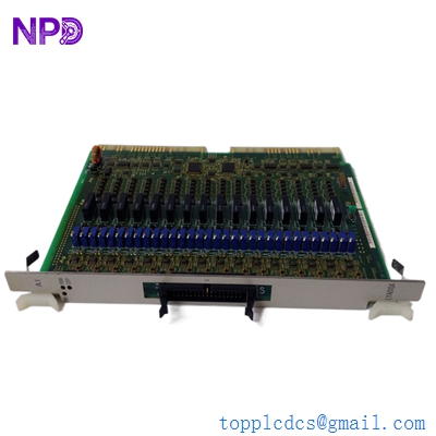
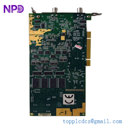
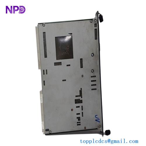
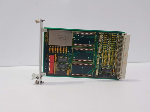
The Kongsberg PSI-100 (Part Number: 37737996 A) is a specialized Printed Circuit Board (PCB) assembly utilized within Kongsberg’s maritime and offshore automation systems. It functions primarily as a process interface or signal conditioning module, designed to bridge the gap between field-level sensors and the central processing units of vessel management or dynamic positioning systems. Its robust design is intended to maintain high signal integrity in electrically noisy industrial environments.
📋 Technical Specifications
- Model Number: 37737996 A
- Series: PSI-100 Interface
- Manufacturer: Kongsberg
- Function: Process Signal Interfacing / Conditioning
- Construction: High-reliability industrial PCB
- Mounting: Card-cage / Rack-mount modular design
- Weight: 0.6 lbs (0.27 kg)
- Country of Origin: Norway
⚙️ Application Areas
- Offshore Drilling and Production Control
- Marine Dynamic Positioning (DP) Systems
- Integrated Bridge and Automation Systems
- Sensor Data Conditioning for Harsh Environments
- Critical Asset Monitoring
🛠️ Operating Instructions & Guidelines
- Installation: This module is designed for insertion into a standardized Kongsberg card cage. Ensure the system is powered down before installation. Align the card carefully with the backplane guides and press firmly until the edge connector is fully seated. Secure the locking mechanism to prevent vibration-induced loosening.
- Environmental Requirements: Operate within a climate-controlled enclosure. Given its role in maritime applications, ensure the card is protected from humidity exceeding 85% and airborne salt, which can cause micro-corrosion on gold-plated contacts.
- Maintenance: Periodic visual inspection for thermal stress (discolored components) is recommended. Ensure the card cage’s integrated cooling or ventilation is unobstructed to prevent heat buildup on the PCB surface.
⚡ Power Sequence & Operation
- Power-On Sequence: 1. Ensure the host rack power supply is stable at 24VDC (typical). 2. Insert the card and confirm all connections are secure. 3. Power up the rack. 4. Observe the PCB-mounted status LEDs; a steady green light usually signifies that the internal logic is powered and the module has successfully completed its initialization.
- Power-Off Sequence: 1. Notify the system operator or controller to place the associated I/O loop into “safe” or “maintenance” mode. 2. De-energize the host rack. 3. Wait for the discharge of local capacitors before removing the card.
- Step-by-Step Operation: 1. Confirm the card is properly recognized by the system software configuration. 2. Verify incoming analog/digital signals at the terminal block using a calibrated multimeter. 3. Monitor the data output in the system diagnostic console to ensure there is no signal jitter or “frozen” values.
❓ Frequently Asked Questions (Q&A)
- What does the “A” revision suffix indicate? The “A” indicates the initial manufacturing release or version of this specific PCB design. When requesting replacements, providing the full part number (37737996 A) ensures you receive a board with the correct hardware firmware and component layout.
- Is this card susceptible to ESD? Yes, like all precision PCBs, it is highly sensitive to Electrostatic Discharge. Always handle the card by the edges or the faceplate and use an anti-static wrist strap when performing any installation or maintenance.
- Can I repair traces on this board if they are damaged? Due to the multi-layer, high-density nature of Kongsberg PCB assemblies, field-level soldering or trace repair is strictly discouraged as it may compromise the reliability of the system and void safety certifications.
- What if the status LED is flashing red? A flashing red LED generally indicates a hardware self-test failure or an internal voltage rail irregularity. Inspect the backplane connector for bent pins or debris; if the issue persists, the module likely requires professional replacement.