
Description
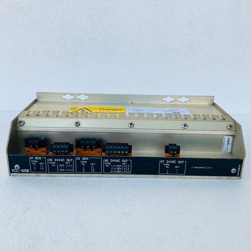
The Kongsberg VCC-690 is a high-reliability power management and voltage regulation module engineered for marine automation architectures. It acts as a specialized controller for stabilizing, converting, and monitoring power distribution lines within integrated control cabinets. Built to withstand continuous maritime vibrations and thermal shifts, this device ensures clean DC power delivery to critical processor racks, communication bridges, and sensitive sensor interfaces.
Technical Specifications
- Model ID: VCC-690
- Device Type: Intelligent Voltage Converter / Power Controller
- Dimensions: 190 mm x 135 mm x 55 mm
- Weight: 0.92 kg
- Country of Origin: Norway
- Input Range: Broad-range industrial DC input configurations
- Output Stability: Highly regulated, low-ripple DC power rails
Application Areas
⚓ Main Engine Room Power Distribution Cabinets
🚢 Integrated Automation Systems (IAS) Power Infrastructure
🌊 Thruster Control Unit Auxiliary Electronics
🏗️ Offshore Vessel Bridge Sensor Power Regulation
🛰️ Marine Switchboard Telemetry Networks
Operational Guidelines
Power-Up / Power-Down Sequence
- Startup: Verify all terminal connectors are locked and clear of loose copper strands. Apply primary input voltage to the VCC-690 unit. Observe the front interface; the diagnostic power LED will cycle through an initialization flash and settle to a solid green state, confirming that the output voltage rails are stabilized and active.
- Shutdown: Isolate the downstream electronic loads by opening their respective branch fuses or breakers. Disconnect the main primary feed breaker supplying the VCC-690. Wait a minimum of 45 seconds to allow internal high-capacity filter capacitors to bleed down completely before servicing any terminal links.
Step-by-Step Standard Operation
- Mounting Verification: Confirm the module is firmly clamped to the enclosure chassis backplate and that ventilation clearance matches system parameters.
- Input Configuration: Check that the input supply line voltages conform strictly to the parameters stamped on the device nameplate.
- Terminal Landing: Secure the input, output, and remote alarm monitoring wires into the spring-cage terminal header blocks.
- Voltage Verification: Power up the module and use the onboard test points with a digital multimeter to confirm precise output regulation.
- Monitoring Loop Link: Integrate the unit’s dry-contact fault relay output into the vessel’s centralized alarm system monitoring loop for real-time health updates.
Frequently Asked Questions
Q: What does an amber or red status LED on the VCC-690 faceplate mean? A: An amber LED typically flags an overcurrent warning or an elevated temperature condition, while a solid red LED indicates an overvoltage trip or an internal circuit failure. Check line loads immediately.
Q: Is it safe to run multiple VCC-690 modules in parallel for higher current demands? A: Parallel load-sharing is model-specific. Refer to your project’s specific electrical schematics to verify if your units are equipped with the forced load-share tracking circuitry before linking output rails.
Q: How does the unit handle sudden voltage spikes common on marine grids? A: The VCC-690 features integrated heavy-duty transient voltage surge suppression (TVSS) circuits designed to clamp line spikes and isolate sensitive downstream logic components from electrical harm.