
Description
🔍 Product Overview
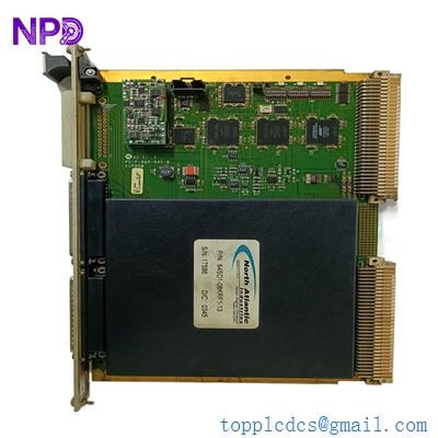
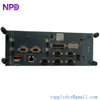
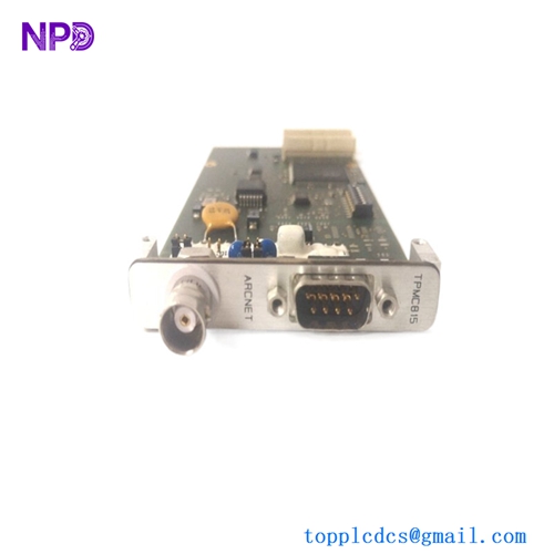
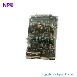
The Liebherr 918149214 is a high-reliability Litronic CAN Module designed for complex communication network routing in heavy-duty industrial machinery. Manufactured by Liebherr Electronic, this module acts as a critical node inside decentralized intelligence systems, facilitating real-time Controller Area Network (CAN) data exchange. It is heavily utilized in high-stress maritime and construction automation to maintain error-free bus communications.

⚙️ Technical Parameters & Specifications
- Module Type: Litronic CAN Module
- Part Number (P/N): 918149214
- Cross-Referenced Board Number: 917828114 / 5.04.527.091
- Product Dimensions: 210 mm x 145 mm x 65 mm
- Net Weight: 1.90 kg
- Country of Origin: Germany
🚀 Application Areas
- Marine Crane Systems: Integrating hoisting, luffing, and slewing control network buses.
- Offshore Winch Control: Processing high-speed sensor feedbacks over distributed networks.
- Liebherr Litronic Machinery: Core communication subsystem for excavators, material handlers, and mining equipment.
- Distributed Industrial I/O: Linking physical fieldbus segments to master controller networks.
📖 Product Usage Instructions
The module must be mounted in a robust, vibration-dampened control panel appropriate for heavy industrial or maritime environments. Connect standard CAN high, CAN low, and shield grounding lines to the dedicated terminal layout to prevent signal distortion. Ensure that correct 120-ohm termination resistors are installed if this unit resides at the physical ends of the CAN bus line.
🌐 Communication Configuration Steps
- IP Address / Network Identification: As an embedded fieldbus device, node configuration is governed via the master Litronic system controller mapping or through dedicated CANopen service tools.
- Station Number: Set the unique node ID (Station Address) using the onboard hardware address selectors or pre-configured software parameters to prevent collision identifiers on the bus.
- Baud Rate: Automatically synchronizes or manual configs to standard industrial network rates (typically 125 kbps, 250 kbps, or 500 kbps) depending on total bus length and topology.
⚡ Power-Up & Commissioning Flow
- Hardware Audit: Verify that internal wiring connections and terminal shields are securely tightened.
- Power Input Check: Confirm auxiliary DC supply meets system ratings (typically 24V DC nominal) prior to energizing.
- LED Initialization: Switch on power and check front-panel LEDs. Status indicator should settle from initialization state to a steady run state.
- Bus Scanning: Initialize a network sweep via the Litronic diagnostic display to confirm that node 918149214 is properly discovered without bus-off errors.
✅ Initial Operation Checklist
- Is the physical casing securely grounded to the backplane?
- Are terminal connections isolated from extreme mechanical vibrations?
- Has the specific station address been checked against the master network topology documentation?
- Are CAN data signals free of frame errors during diagnostic trace mode?
❓ Common Questions (Q&A)
Q: What causes a continuous red error indicator on the module? A: This usually implies a heavy bus error state, missing termination resistors, reversed CAN_H/CAN_L lines, or a conflicting station node ID. Q: Can this unit replace older revision Litronic modules directly? A: Yes, the 918149214 can replace matching functional series, but firmware version compatibility should be cross-checked with the main controller system. Q: Is specific routine maintenance required for the casing? A: No internal maintenance is necessary. Keep the external terminals clear of oxidation and ambient moisture, particularly in offshore marine environments.