
Description
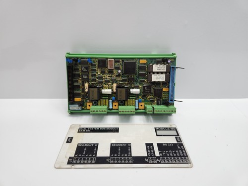
The Lyngso Marine (STN Atlas) SAM 401 Dual System Bus Module is a critical interface component designed for sophisticated maritime automation and navigation systems. It serves as a redundant communication bridge, facilitating high-speed, reliable data exchange between distributed control processors, sensor arrays, and operator stations within the SAM 401 series architecture. Its “Dual System” designation underscores its role in maintaining data integrity through hardware redundancy, which is vital for fail-safe operation in shipboard bridge and engine room automation.
📋 Technical Specifications
- Series: SAM 401 (Integrated Automation System)
- Function: Dual-Bus Communication/Interface Module
- Redundancy: Integrated dual-channel bus architecture for fault tolerance
- Communication: Proprietary STN Atlas/Lyngso fieldbus protocol
- Mounting: Standard SAM 401 cabinet rack-mount
- Operating Temp: -15°C to 55°C
- Dimensions: Standard modular electronics casing
- Weight: 2.2 lbs (1.0 kg)
- Country of Origin: Germany
⚙️ Application Areas
- Integrated Ship Control Systems (ISCS)
- Engine Room Monitoring and Alarm Systems
- Navigation and Dynamic Positioning Data Distribution
- Redundant Fieldbus Communication Networks
- Large-Scale Commercial and Military Vessel Automation
🛠️ Operating Instructions & Guidelines
- Installation: Secure the module within an EMC-shielded cabinet. Ensure the dual-bus (Channel A and Channel B) cabling is routed through separate conduits to prevent a single point of failure (e.g., cable crush or localized fire) from disabling both communication channels simultaneously.
- Environmental Requirements: Operate within a climate-controlled environment. Because this module manages critical data, ensure the cabinet is free of metallic dust or conductive contaminants which can trigger intermittent bus noise.
- Maintenance: During scheduled refits, verify the integrity of the bus termination resistors. Perform a “Communication Loopback” test using the SAM 401 diagnostic software to ensure both Channel A and Channel B are reporting healthy packet transmission rates.
⚡ Power Sequence & Operation
- Power-On Sequence: 1. Energize the 24VDC system power supply. 2. Verify both power rails (if dual-fed) are active. 3. Observe the “Bus Status” LEDs on the front faceplate; green indicators for both channels confirm a stable link. 4. Wait for the system controller to acknowledge the module during the boot scan.
- Power-Off Sequence: 1. Ensure the automation system is in a “System Standby” or “Service” mode. 2. De-energize the cabinet power. 3. Disconnect cables only when servicing the bus interface hardware.
- Step-by-Step Operation: 1. Configure the node address (DIP switches or software-defined) as per the vessel’s network map. 2. Monitor the “Data Transfer” LEDs to observe active bus traffic. 3. Use the system diagnostic console to check for “Bus Error” counters, which indicate noise or termination issues.
❓ Frequently Asked Questions (Q&A)
- What does the “Dual System Bus” offer compared to a single bus? It provides fault tolerance. If one physical communication path is damaged or experiences high interference, the module automatically fails over to the second bus to ensure that critical alarms and control data continue to reach the master controller.
- How can I tell if one of the busses has failed? The front-panel LEDs provide immediate feedback. Typically, an LED will change color or extinguish if it stops receiving a valid clock/data signal from its respective bus channel.
- Is this module hot-swappable? Generally, no. Removing this module while the system is live will result in a communication breakdown and likely trigger an “I/O System Fault” alarm on the vessel bridge.
- What is the common cause of intermittent bus errors? Loose connections or improper cable shielding. In marine environments, vibration can loosen terminal screws; periodic tightening is essential to prevent data collisions and packet loss.