
Description
🌐 Product Overview
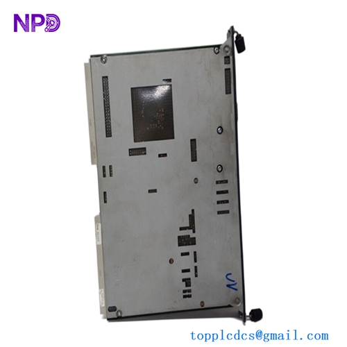
The MAN 51.27721-7112 is a rugged, industrial-grade multi-function indicator display panel (MFR-Display) engineered specifically for MAN diesel engines, heavy commercial vehicles, and marine propulsion machinery control systems. Operating as a critical human-machine interface (HMI), this display reads complex telemetry parameters directly from the engine’s centralized electronic management unit via high-speed communication networks. It delivers real-time operational readouts, diagnostic trouble codes (DTCs), and maintenance alerts to operators, helping prevent equipment down-time and ensuring optimal mechanical performance under severe operating profiles.
⚙️ Technical Specifications
- Part Number: 51.27721-7112 (MFR Display Series)
- Dimensions: 165mm x 115mm x 60mm
- Weight: 0.72 kg
- Origin: Germany
- Display Core: High-visibility, anti-glare industrial graphical LCD matrix
- Operating Voltage: 24V DC nominal (18V to 32V DC automotive/marine operational range)
- Communication Interface: Integrated high-speed J1939 CAN bus lines and K-line diagnostics
- Ingress Protection: IP65 rated front face for protection against water spray, oil mist, and dust ingress
🚀 Application Fields
- Heavy-Duty Commercial Vehicles: Dashboard integration for MAN long-haul transport trucks, construction equipment, and specialized logistics fleets.
- Marine Propulsion Networks: Localized engine room diagnostic monitor or secondary bridge display panel for MAN marine diesel engines.
- Industrial Power Generation: Monitoring station for stationary MAN diesel generators and backup auxiliary power units (APUs).
- Agricultural Machinery: High-reliability parameter tracker on large-scale harvesting equipment and industrial utility tractors.
📖 Product Instructions
- Panel Installation: Mount the display into the vehicle dashboard or engine control console cutout. Secure the panel using the provided rear-mount retention brackets, verifying that the perimeter sealing ring sits flush against the console surface.
- Harness Termination: Plug the standardized multi-pin automotive connector into the rear socket of the display until the retention clip clicks into place. Route the CAN bus wiring harness clear of high-voltage starter motors and alternators.
- Contrast & Backlight Calibration: Upon initial configuration, enter the local configuration menu using the front tactile keys to adjust the display brightness matrix to match ambient workspace visibility conditions.
✅ Initial Startup Checklist
- Verify that the auxiliary electrical distribution system supplies a stable 24V DC feed to the display pins.
- Confirm that the communication wiring harness is equipped with standard 120-ohm terminating resistors where required by the CAN network topology.
- Power up the vehicle ignition or control station panel; the display should pass through its internal diagnostic splash screen without flagging memory verification faults.
- Verify that engine metrics (RPM, coolant temperature, oil pressure) populate the screen within a few seconds of engine startup, confirming active data communications.

🛠️ Maintenance & Care
- Connector Integrity Audits: Inspect the rear multi-pin plug connection annually during standard mechanical service overhauls to ensure chassis vibrations haven’t backed off the pins.
- Display Screen Care: Wipe the front graphical screen exclusively with a soft, anti-static microfiber cloth slightly dampened with clear water. Never apply abrasive scouring pads or industrial degreasers.
- Firmware Verification: During scheduled system maintenance checkups, cross-reference the unit’s running application version against manufacturer specifications to ensure compatibility with any engine control module (ECM) firmware updates.
⚠️ Safety Precautions
- Isolate Electrical Systems: Always disconnect the main battery isolation switch or lock out the control breaker before unplugging the display wiring harness to avoid inductive arc damage.
- Menu Restraint Warning: Operators must never navigate dense diagnostic sub-menus or alter critical operational thresholds while the vehicle is in active transit or the engine is loaded under critical maneuvers.
- Splicing Hazards: Do not cut, splice, or alter the impedance parameters of the twisted-pair CAN bus lines directly feeding the unit, as this can corrupt timing signals across the entire engine network.
🔍 Troubleshooting & FAQ
- Q: The display screen boots up normally, but all parameter values show blank dashes or trace lines.
- A: This indicates a communication link break between the display and the engine control module. Inspect the J1939 CAN bus data lines for short circuits, loose terminal pins, or a blown network fuse.
- Q: The LCD display flickers continuously or reboots randomly when the engine cranks.
- A: This behavior points to excessive voltage drops on the primary 24V DC electrical line during high starter motor draw. Check battery health, clean corroded battery terminals, and review the sizing of your electrical distribution wires.
- Q: Can the displayed fault codes be cleared directly from the front panel interface?
- A: Active active engine faults cannot be cleared until the physical mechanical defect is resolved. However, historical log codes can be wiped via the service menu if the user inputs the certified technician authorization passcode.