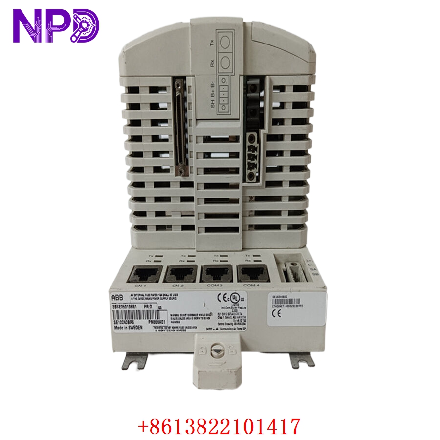

Description
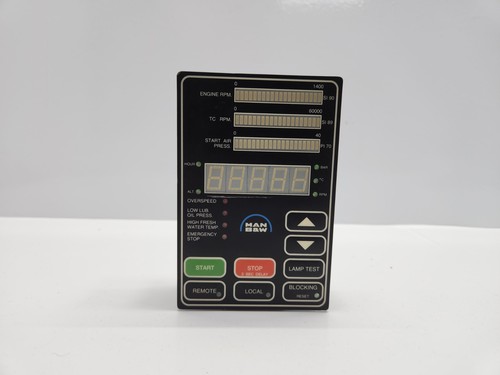
The MAN B&W 2101544-1 OB (Output/Bus) Module, Revision 1.14, is a specialized electronic control component utilized within the engine management systems of MAN B&W marine diesel engines. This module serves as a high-reliability interface for coordinating engine operations, including fuel injection timing, exhaust valve actuation, and overall performance monitoring via the engine control system (ECS).
⚙️ Technical Specifications
- Dimensions: 280 mm x 220 mm x 60 mm
- Weight: 1.1 kg
- Country of Origin: Denmark / Germany
- Supply Voltage: 24V DC
- Operating Temperature: -20°C to +75°C
- Housing: Industrial-grade modular casing designed for high-vibration maritime engine environments
🏗️ Application Areas
- MAN B&W Two-Stroke Electronic Engines
- Alpha Lubricator Control Systems
- Electronic Fuel Injection (EFI) Management
- Engine Control System (ECS) Data Distribution
- Marine Auxiliary and Propulsion Engine Monitoring
📖 Product Usage Instructions
This module should be installed in a climate-controlled cabinet within the engine room or control room. Ensure the module is mounted securely to the backplane to prevent contact issues caused by engine vibration. Always use anti-static protection when handling the module, as the internal logic circuitry is sensitive to ESD. Secure all terminal connections to prevent loosening over time.
🌐 Communication Configuration Steps
- IP Address: As a bus-integrated module, IP parameters are managed by the main Engine Control System (ECS) cabinet. Access the system terminal to assign the module’s node address.
- Station Number: The station ID is configured via hardware jumpers on the module’s backplane or through the service software interface to ensure unique identification on the CAN/Bus network.
- Baud Rate: The communication speed is fixed by the system bus requirements (typically 500 kbps for engine control networks). Ensure the configuration file matches the master controller settings.
⚡ Power-Up Debugging Flow
- Verify 24V DC power input at the chassis bus.
- Observe the “Bus Status” and “Power” LEDs; both should be solid green under normal operating conditions.
- If the “Bus Status” LED flashes, it indicates a communication loss or network interference.
- Check the service tool for any active diagnostic error codes related to the module’s address.
- If the module fails to initialize, perform a power cycle to the cabinet slot.
✅ Initial Run Checklist
- Validate that the module firmware (Rev 1.14) is compatible with the overall engine software version.
- Monitor real-time feedback values from actuators connected to this module.
- Check for “Communication Time-out” alarms in the central ECS HMI.
- Ensure all cable shields are properly grounded to the cabinet’s earth bus.
- Save the module’s operational logs to your service computer after the first hour of steady-state operation.
❓ Frequently Asked Questions (Q&A)
Q: What does “OB” stand for in this context? A: OB generally refers to “Output/Bus” functionality, indicating that the module is designed to handle control outputs while maintaining communication across the internal engine control bus.
Q: Can I use this module for different engine models? A: Compatibility depends entirely on the engine software configuration. Always ensure the module part number and revision match the specifications in your vessel’s technical manual.
Q: How do I update the firmware? A: Firmware updates must be performed using the MAN B&W-certified Service Tool via the dedicated programming port. Never interrupt power during an update process.
Q: Why is the module generating a heat-sink alarm? A: This usually indicates poor airflow within the cabinet or a potential short circuit on one of the output channels. Inspect the cabinet cooling fans and check field wiring for short-to-ground faults.