
Description
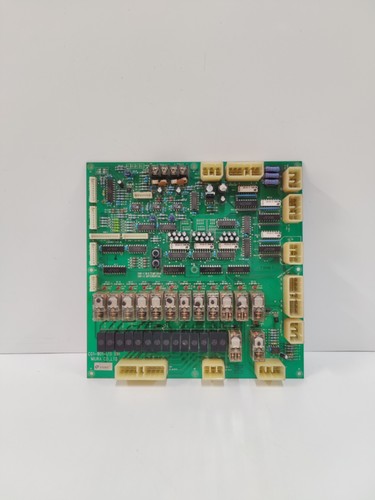
The MIURA CG1-901-I/O 01H is a high-reliability printed circuit board (PCB) designed specifically for Miura steam boiler control systems. As an essential I/O module, this board facilitates the interface between the boiler’s central control unit and field sensors, such as pressure transmitters, water level probes, and combustion safety devices. It is engineered to maintain precise control over boiler operation to ensure safety and thermal efficiency.
📋 Technical Specifications
🔹 Part Number: CG1-901-I/O 01H 🔹 Component Type: I/O Interface PCB 🔹 Series: Miura Boiler Control Series 🔹 Application: Sensor Input / Actuator Output Management 🔹 Weight: Approximately 0.40 kg 🔹 Origin: Japan
🚀 Application Fields
⚡ Industrial Steam Boiler Control 🏭 Thermal Energy Management ⚙️ Automated Combustion Safety Systems ⚓ Marine Boiler Supervision
🛠️ Product Instructions
The CG1-901-I/O 01H board is intended for installation within the Miura boiler control panel enclosure. To install, ensure the main power is disconnected. Slide the board into the designated rack guides, ensuring that the backplane connector aligns perfectly to avoid pin damage. Given the sensitive nature of these boards in a boiler environment, always ensure the cabinet is dry and free of steam leaks or high-humidity exposure.
⚙️ Communication & Configuration Steps
⚙️ Address Mapping: Configuration is typically managed through the boiler’s main CPU or via onboard DIP switches that define the input/output addressing scheme for the specific boiler model. ⚙️ Station Number: The board functions as a node on the local control bus; ensure that the physical switch settings on the board correspond to the “Node” or “Slot” address required by the main controller’s software. ⚙️ Baud Rate: Communication is governed by Miura’s proprietary bus protocol. Ensure all cabling is properly shielded and the bus is correctly terminated at both ends to prevent data signal noise.
🔋 Power-up Debugging Process
✅ Step 1: Ensure all wiring terminals (input/output) are securely tightened. ✅ Step 2: Apply power to the control panel and check for the “Ready” indicator on the board’s edge. ✅ Step 3: Use the boiler’s control interface to confirm that input signals (e.g., water level or steam pressure) are being read accurately. ✅ Step 4: Perform a brief manual output test (e.g., cycling an auxiliary pump or valve) to verify that the board’s output relays are functioning correctly.
📋 First-time Operation Checklist
✔️ Confirm that the part number matches the board being replaced, especially the revision (01H). ✔️ Inspect all ribbon cables and connectors for signs of oxidation or wear. ✔️ Verify the power input voltage (typically 24V DC or as specified on the board label) before final startup. ✔️ Confirm that the boiler’s safety parameters are fully updated in the main controller following the board installation.
❓ Frequently Asked Questions (Q&A)
❓ Q: What does the “I/O Error” on the main display usually mean? 💡 A: An I/O error often indicates a loss of communication between the CPU and this board, or a fault in one of the connected sensor loops. Check the cables connecting the board to the terminal blocks.
❓ Q: Is this board susceptible to heat damage? 💡 A: Boiler control cabinets are designed to be cool, but excessive heat can shorten the lifespan of the PCB components. Ensure the cabinet’s cooling fan is operational and the air filters are clean.
❓ Q: Can I replace individual relays on this PCB? 💡 A: While relays are a common failure point, they are often soldered directly to the board. For safety-critical boiler components, it is strongly recommended to replace the entire PCB rather than attempting component-level repair to maintain safety certification.