
Description
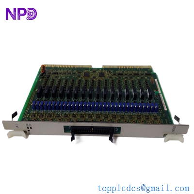
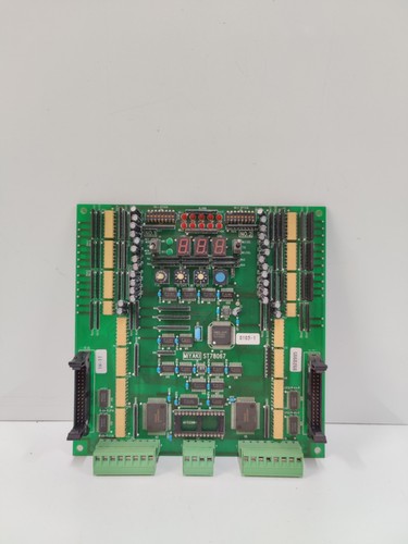
The MIYAKI ST78067 is a precision-engineered printed circuit board (PCB) used primarily in specialized industrial control and automation applications. Often utilized in machinery control or proprietary automation systems, this board serves as a core logic component, facilitating signal processing, input/output management, and system-wide synchronization. It is built for reliability in high-cycle environments where consistent electronic performance is critical for machine uptime.
📋 Technical Specifications
🔹 Part Number: ST78067 🔹 Manufacturer: Miyaki 🔹 Component Type: Logic/Control PCB 🔹 Function: Signal Processing and I/O Management 🔹 Weight: Approximately 0.30 kg 🔹 Origin: Japan
🚀 Application Fields
⚡ Industrial Automation Controllers 🏭 Precision Manufacturing Machinery ⚙️ Specialized Robotic Logic Systems 📊 Automated Quality Control and Monitoring
🛠️ Product Instructions
The ST78067 PCB is designed for rack or chassis mounting within an industrial control enclosure. To install, ensure the main power is fully disconnected. Utilize standard anti-static handling procedures to avoid damaging the integrated circuits. Slide the board carefully into its designated slot, ensuring that the backplane pins are properly aligned. Once seated, ensure the retaining screws are secured to maintain proper grounding and prevent vibration-induced damage.
⚙️ Communication & Configuration Steps
⚙️ Address Mapping: Configuration is typically managed through the system’s primary controller or via physical switches (DIP switches) located on the board. Ensure these settings match the system integration map. ⚙️ Station Number: The station ID identifies this module within the machine’s local communication bus. This is configured during the initial system setup or replacement process. ⚙️ Baud Rate: The communication speed is factory-optimized for the Miyaki system architecture. If you are integrating this into a larger network, ensure the bus terminators are correctly placed to prevent data signal reflection.
🔋 Power-up Debugging Process
✅ Step 1: Double-check all I/O cabling to ensure no short circuits exist in the field wiring. ✅ Step 2: Apply power and monitor the status LEDs on the PCB face. A steady “Ready” or “Power” light indicates successful voltage regulation and system initialization. ✅ Step 3: Access the machine’s maintenance interface to verify that the board is communicating successfully with the master processor. ✅ Step 4: Execute a “Loop Test” on the critical inputs to ensure the board is accurately detecting sensor states.
📋 First-time Operation Checklist
✔️ Confirm the board version (ST78067) is compatible with your current machine firmware. ✔️ Inspect the PCB for any signs of physical damage or oxidation on the gold-plated contact pins. ✔️ Verify that the power supply rails (typically 5V/12V/24V) are stable and free of noise. ✔️ Perform a functional test of a non-critical output relay to verify the board’s logic execution.
❓ Frequently Asked Questions (Q&A)
❓ Q: What does a blinking error LED on the ST78067 typically mean? 💡 A: A blinking error LED usually indicates a “Watchdog” timeout or a communication loss. This often occurs if the board is failing to receive a consistent “heartbeat” signal from the central PLC or if a bus cable has been disturbed.
❓ Q: Can I repair a damaged trace on this board? 💡 A: Due to the complexity of industrial PCBs, it is strongly recommended not to repair traces manually, as this can lead to unstable logic levels and potential machine safety issues. Always opt for a verified replacement unit.
❓ Q: How does this board interface with sensors? 💡 A: The ST78067 utilizes high-speed optocouplers to isolate the sensitive board logic from the often “noisy” electrical environment of industrial sensors, ensuring stable data collection even in high-interference areas.