
Description
🌐 Product Overview
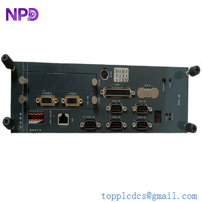
The Molex SST-ESR2-CLX-RLL is a high-performance, slot-in communication module designed to seamlessly interface Allen-Bradley ControlLogix PLC systems with remote fieldbus networks. This specialized module enables direct connectivity to serial networks and EtherNet/IP protocols, facilitating rapid data exchange and high-speed telemetry translation. Engineered for process synchronization and heavy-duty industrial integration, it allows industrial automation engineers to bridge legacy field infrastructure with modern distributed control networks without sacrificing backplane throughput or processing deterministic speeds.

⚙️ Technical Specifications
- Series: SST Communication Module Component Line
- Dimensions: 140mm x 35mm x 110mm (Standard Single-Slot ControlLogix Form Factor)
- Weight: 0.38 kg
- Origin: United States / Canada
- Backplane Compatibility: Rockwell Automation Allen-Bradley ControlLogix Chassis (1756 Series)
- Current Draw: 1.5A @ 5V DC; 0.005A @ 24V DC (Backplane Powered)
- Communication Ports: 1 x RJ-45 EtherNet/IP Port, Dedicated Industrial Serial Channels
- Isolation Rating: 500V DC continuous isolation between network ports and backplane logic
🚀 Application Fields
- Factory Automation Grid Integration: Connecting ControlLogix processors to localized manufacturing grids, barcode scanners, and variable frequency drives (VFD).
- SCADA Telemetry Aggregation: Acting as a high-speed data hub collecting digital parameters from remote telemetry units (RTUs) in water treatment plants.
- Process Line Interfacing: Bridging specialized weighing systems, flow meters, and analytical instrumentation running legacy serial communication into modern control structures.
- Automated Material Handling: Coordinating real-time conveyor sorting lines, picking machinery, and automated guided vehicles (AGVs).
📖 Product Instructions
- Chassis Slotting: Ensure the ControlLogix chassis power supply is turned off. Align the module circuit board with the top and bottom chassis card guides, then slide the SST-ESR2-CLX-RLL firmly into the selected slot until the locking tabs click into position.
- Network Connection: Connect a standard Cat5e or Cat6 industrial Ethernet cable to the RJ-45 network interface port, routing it clear of adjacent high-voltage motor contactor leads.
- Module Mapping: Open the Rockwell Automation RSLogix 5000 / Studio 5000 environment, add the module to the I/O configuration tree under the local backplane, and configure the input/output connection tag array sizes.
✅ Initial Startup Checklist
- Verify that the ControlLogix chassis power supply has sufficient capacity to accommodate the 1.5A current draw at 5V DC.
- Confirm that the communication patch cords and serial terminal block wiring connections match the designated network topology blueprints.
- Turn on the chassis power and observe the front-facing multi-segment alphanumeric display or LED indicators; look for a scrolling “OK” or normal node status read-out.
- Verify from the configuration tool that the backplane firmware driver successfully completes its handshaking protocol with the module processor.
🛠️ Maintenance & Care
- Mechanical Tightness: Check the module retention latches during semi-annual plant shutdowns to ensure the unit remains seated despite continuous machinery vibrations.
- Backplane Pin Cleaning: If the module is extracted for system modification, inspect the backplane gold-plated connectors for dust or oxidation, cleaning safely with specialized electronic contact cleaner if necessary.
- Log Analysis: Periodically monitor the network collision statistics and packet error retries in the configuration management console to identify cable degradation early.
⚠️ Safety Precautions
- Prevent Live Insertion: Do not insert or remove the communication module while backplane power is active, as arcing across the data bus pins can damage both the module and the chassis backplane.
- Electrostatic Charge Management: Keep the card in its anti-static protective shield until physical installation, and touch a grounded metal frame before handling the exposed electronics to avoid static puncture.
- Network Isolation Defenses: Ensure that appropriate industrial firewalls or managed switches separate the module’s EtherNet/IP network layer from corporate enterprise IT networks to minimize cybersecurity vulnerabilities.
🔍 Troubleshooting & FAQ
- Q: The module display scrolls a specific hex error code (e.g., E1, E2) and communication halts.
- A: Internal hex fault codes typically point to a firmware checksum error, configuration mismatch, or an unresolved backplane communication timeout. Verify that the module’s electronic keying settings in Studio 5000 match the physical hardware revision.
- Q: The Ethernet “LINK” light is off, even though a network patch cable is securely plugged in.
- A: This indicates a loss of physical layer connectivity. Check the remote network switch port configuration, verify the patch cable integrity using a network tester, and ensure the distance does not exceed standard Ethernet parameters.
- Q: Can the serial and Ethernet channels on this module be operated simultaneously to cross-communicate data?
- A: Yes, the dual-processor core architecture allows the module to manage simultaneous serial data parsing and high-speed EtherNet/IP transactions, mapping both data structures into a unified tag database shared with the ControlLogix CPU.