
Description
📝 Product Overview
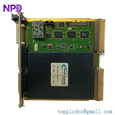
The Motorola 01-W8998B (Part Number: 84-W8999B01C) is a high-reliability, industrial-grade Printed Circuit Board (PCB) card designed for specialized telemetry, radio base station communications, or legacy distributed control systems. Manufactured to Motorola’s rigorous engineering standards, this module handles low-level data routing, signal conditioning, or transceiver interface tasks, ensuring high noise immunity and stable logic execution within rugged electronic enclosures.
⚙️ Technical Specifications
- 📐 Dimensions: 180 mm x 120 mm x 18 mm
- ⚖️ Weight: 0.28 kg
- 🌍 Country of Origin: United States
🏭 Applications
- Industrial radio communication infrastructure networks
- Legacy SCADA and telemetry outstation processing
- Dedicated data routing and signal conditioning interfaces
- Plant-wide emergency communication control racks
🛠️ Usage Instructions
- Always wear an earthed anti-static wrist strap (ESD protection) when handling or removing the card from its protective static shielding bag.
- Inspect the gold-plated edge connector fingers for cleanliness; wipe gently with an isopropyl alcohol swab if oxide layer buildup is present.
- Align the card carefully within the sub-rack guide rails before firmly pushing it into the backplane socket to avoid bending connector pins.
- Do not plug or unplug the board while the sub-rack power distribution unit is switched on.
🔧 Mechanical Installation Requirements
- Fixing Method: Vertical slide-in slot installation into a standard card cage chassis, secured using the integrated top and bottom front-panel plastic extraction levers.
- Space Clearance: Follow standard multi-slot card cage spacing parameters (typically a 20 mm pitch) to prevent physical contact with adjacent circuit cards.
- Heat Dissipation: Relies on the chassis fan tray for forced-air cooling. Ensure air filters on the enclosure intake vents are clean to maintain a localized air temperature below 55°C.
🔌 Electrical Wiring Guide
- Terminal Definitions: * Edge Connector Pins A1–A4: Logic Power Supply Inputs (+5V DC / +12V DC / Ground)
- Edge Connector Pins B1–B12: High-Speed Serial Interface and I/O Data Line Contacts
- Edge Connector Pins C1–C4: Dedicated Signal Ground and Cable Shield Return Paths
- Wire Gauge: Backplane connections are predefined by the motherboard layout. External connections from the backplane terminal blocks should use 0.5 mm² to 1.0 mm² (20 to 18 AWG) shielded twisted-pair cables for data lines.
- Grounding Norms: The chassis hosting the backplane must be bonded to the central equipment room star-ground network. Ensure the PCB’s ground plane securely interfaces with the rack’s frame grounding clips.
📡 Communication Configuration
- IP Address: Not applicable. This module operates via low-level bus-oriented parallel logic or point-to-point synchronous serial protocols rather than a direct TCP/IP architecture.
- Station ID: Configured physically via hardware jumper pins or an on-board 8-bit DIP switch array to map the card’s specific bus address register within the processing cluster.
- Baud Rate: Automatically locks onto the synchronized clock frequency of the master CPU bus controller, typically operating at legacy serial speeds (e.g., 19200 bps) or megabit backplane speeds.
❓ Frequently Asked Questions (Q&A)
- Q: Why is the board failing to register or initialize in the slot?
- A: Verify that the card is fully seated in the backplane socket, check that the hardware DIP switches are set to a unique address node, and inspect the backplane for bent pin segments.
- Q: Can this card be used across different sub-rack models within the same product line?
- A: Yes, provided the firmware revision matches the system master configuration requirements and the backplane pin-out profiles are fully compatible.
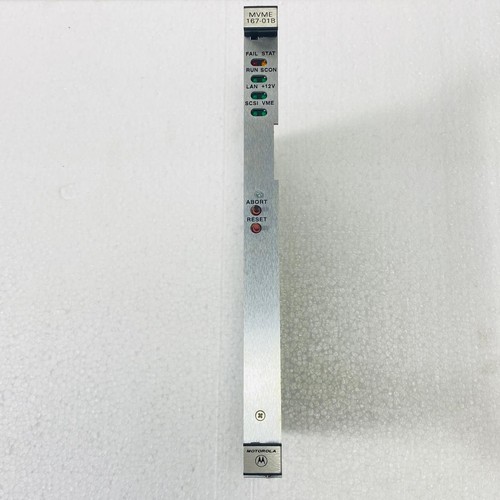
- Q: What indicates a hardware failure on the board?
- A: Most configurations use an onboard red “ERR” or “FAIL” micro-LED to signal a watchdog timeout or a localized voltage regulator breakdown during self-test sequences.