
Description
Product Overview
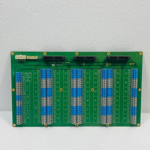
The MRC MTB-5000 (part number P90011C) is a high-density, heavy-duty interface terminal board engineered for industrial process control and automation systems. It functions as a centralized wiring distribution hub, bridging field instruments, sensors, and actuators with the primary I/O processing racks. Built with robust isolation pathways, it ensures stable signal routing, reduces electrical noise interference, and simplifies cabinet field terminations in complex control loops.
Technical Specifications
- Model ID: MTB-5000
- Part Number: P90011C
- Dimensions: 185 mm x 110 mm x 48 mm
- Weight: 0.62 kg
- Country of Origin: United States
- Terminal Type: Multi-point screw clamp terminal blocks
- Voltage Rating: 24–120 VDC / VAC operational range
Application Areas
⚙️ Distributed Control System (DCS) Field Distribution Panels
🏭 Petrochemical and Refinery Automation Cabinets
⚡ Power Generation Plant Control Rooms
🌊 Water and Wastewater Treatment Facility Panel Wiring
🏗️ Heavy Machinery Signal Junction Boxes
Operational Guidelines
Power-Up / Power-Down Sequence
- Startup: Isolate all external field power loops connected to the board. Mount the MTB-5000 securely onto the cabinet backplate or chassis rails. Connect the master I/O bus cable from the processor rack. Energize the field loops sequentially, checking for correct polarity and voltage levels across each terminal block channel.
- Shutdown: De-energize the primary circuit breakers feeding the field instruments. Disconnect the main system interface cable from the board link. Once all channels are verified dead with a multimeter, proceed to loosen terminal screws or remove the physical board module for maintenance.
Step-by-Step Standard Operation
- Chassis Bonding: Connect a low-impedance ground wire to the board’s dedicated grounding lug to ensure proper shielding.
- Wire Preparation: Strip the field wires to the recommended length and fit them with insulated ferrule terminals for optimal contact.
- Channel Termination: Insert field wires into their designated screw clamp terminals according to the loop drawing matrix and tighten securely.
- Signal Testing: Apply loop power and use test points on the board to confirm stable current/voltage translation to the master I/O card.
- Cable Management: Secure the wire bundles using cable ties to prevent strain on the terminal block physical solder joints.
Frequently Asked Questions
Q: What causes a specific channel on the MTB-5000 to drop signal? A: This is most commonly caused by a loose screw clamp or a cold solder joint from excessive wire strain. Check the tension on the terminal block and inspect the board backplane for physical track damage.
Q: Does the P90011C board include onboard fuse protection? A: Depending on the specific system configuration, certain channels may support plug-in fuse links. Check your engineering BOM to see if external fuse isolation is required for your specific field loop deployment.
Q: Can this terminal board handle high-voltage AC mains wiring directly? A: The board is rated for standard industrial control signal voltages. Running raw high-voltage power lines exceeding its listed specifications will cause arc-over damage and destroy the connected I/O processing cards.