
Description
🌐 Product Overview
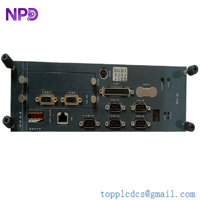
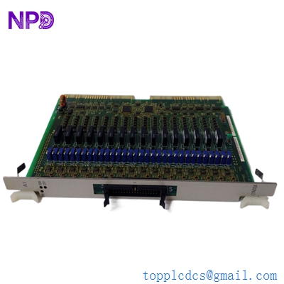
The MRC PA-271 is a rugged, industrial-grade power amplifier engineered to deliver highly stable, linear signal amplification for critical control systems, testing equipment, and electro-mechanical transducers. Built to withstand continuous operation in demanding environments, this amplifier combines precise thermal management with low-distortion output characteristics. It acts as a reliable interface component for converting low-level control signals into high-current power driving outputs, ensuring seamless operation across automated production lines and testing facilities.
⚙️ Technical Specifications
- Series: Heavy Industrial PA Series Instrumentation & Control Amplifiers
- Dimensions: 132mm x 483mm x 380mm (Standard 3U Rackmount Chassis)
- Weight: 8.50 kg
- Origin: United States / European Union (Depending on manufacturing site)
- Input Signal Range: 0 to ±10V DC / 4-20mA (Configurable)
- Frequency Response: DC to 20 kHz (Flat response profile)
- Output Power Capacity: 250W Continuous (4-Ohm / 8-Ohm load matched)
- Cooling System: Internal forced-air cooling fan with variable speed control
🚀 Application Fields
- Vibration Testing Systems: Driving electro-dynamic shakers used in environmental stress screening (ESS) for aerospace and automotive parts.
- Actuator Control: Powering large proportional servo valves and industrial magnetic coils that require high-current stability.
- Acoustic Measurement: Supplying clean power to specialized acoustic transmitters and underwater sonar transducer testing arrays.
- Research and Development: Serves as a flexible laboratory power amplifier for driving high-inductive or capacitive experimental loads.
📖 Product Instructions
- Rack Installation: Slide the PA-271 into a standard 19-inch electronic equipment rack. Secure the front panel ears to the rack frame using heavy-duty M6 screws, ensuring that the front intake and rear exhaust ventilation pathways are completely unblocked.
- Input and Output Signal Wiring: Connect the low-level signal source to the shielded BNC or terminal block input connectors. Terminate the heavy-gauge load cables to the high-current output binding posts, paying strict attention to polarity markings to ensure proper phase alignment.
- Gain and Bias Configuration: Before turning on the system, set the front-panel attenuation knob to its maximum counter-clockwise position (zero output). Adjust the input sensitivity switch on the rear panel to match the nominal voltage output of your upstream controller.
✅ Initial Startup Checklist
- Check that the local AC mains voltage matches the amplifier’s factory configuration setting (115V AC or 230V AC).
- Verify that the total impedance of the connected load does not fall below the minimum rated specification (typically 4 Ohms).
- Turn on the primary power switch and confirm that the green “Power/Ready” LED illuminates and the cooling fan kicks on.
- Slowly increase the front gain dial while monitoring the red “Clip/Overload” LED to ensure the signal remains clean and undistorted under full operational load.

🛠️ Maintenance & Care
- Dust Filtration Maintenance: Vacuum or wash the removable front-panel dust filter every three months to prevent internal heat build-up and maintain optimal airflow.
- Internal Component Inspection: During scheduled facility shutdowns, check internal circuit boards for any signs of heat discoloration and ensure all internal wiring harness connectors are seated firmly.
- Output Binding Post Inspection: Inspect the heavy-duty output terminals regularly for any surface oxidation or loosening caused by high-current thermal cycling.
⚠️ Safety Precautions
- High Voltage Threat: Hazardous voltages are present at the output terminals when the unit is driven at full capacity. Never touch exposed terminal conductors while the amplifier is operating.
- Proper Earth Grounding: Always utilize a 3-wire power cord connected to a verified safety earth ground to prevent chassis electrical shock hazards.
- Avoid Hot-Plugging: Do not connect or disconnect input signal sources or output load cables while the amplifier is powered on, as this can trigger catastrophic inductive kickback damage.
🔍 Troubleshooting & FAQ
- Q: The front panel “Fault” LED turns on and the output signal drops immediately.
- A: This indicates that the internal protection circuit has engaged due to an over-temperature, short-circuit, or over-current condition. Turn off the power, disconnect the load, and check for an explicit short-circuit in your output wiring or transducer coil.
- Q: There is a persistent 50Hz/60Hz background hum present in the amplified output signal.
- A: This is typically caused by a ground loop in the signal path. Ensure that the input signal cable shield is grounded at only one end, or utilize a high-quality signal isolation transformer between the controller and the amplifier input.
- Q: The “Clip” LED flashes frequently during standard operation. What adjustment is required?
- A: Frequent flashing means the input signal is driving the amplifier beyond its linear voltage rails, causing output distortion. Reduce either the output level of your upstream signal source or back off the front-panel gain dial until the LED only flashes briefly during absolute peak signal levels.