Description
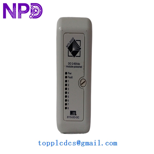
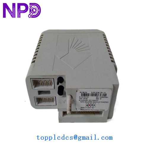
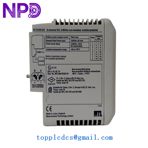
- Model: 8115-DO-DC
- Brand: MTL (Eaton MTL Instruments)
- Series: MTL 8000 Series (Distributed I/O)
- Core Function: Drives field devices like solenoid valves and relays in process environments
- Condition: New Surplus (Original original, never commissioned, non-refurbished)
- Type: Digital Output Module (DO)
- Key Specs: 8 Channels | 24V DC | Isolated Outputs
- Number of Channels: 8 isolated channels
- Output Voltage: 24V DC (derived from field power)
- Output Current: Max 0.5A per channel (subject to total module limits)
- Isolation: 500V AC channel-to-system / 50V AC channel-to-channel
- Response Time: < 10ms (Turn-on/Turn-off)
- Status Indicators: Per-channel LED (Yellow for Active) + Module Status LED
- Diagnostics: Open and short circuit detection (load dependent)
- Operating Temperature: -40°C to +70°C
- Relative Humidity: 5% to 95% (Non-condensing)
- Safety Approvals: ATEX / IECEx for Zone 2 (when installed in appropriate enclosure)
Installation & Configuration Guide
Phase 1: Pre-Installation (10 Minutes)
⚠️ Safety Protocol:
- Ensure the area is safe or confirmed non-hazardous before opening any enclosures.
- Confirm the 24V DC field power supply is stable and within the ±10% range.
- Check the I/O bus carrier for debris or bent pins.
Backup & Documentation:
- Identify the specific slot in the MTL 8000 carrier.
- Note the tag numbers of the solenoid valves or relays connected to the existing module.
Phase 2: Removing the Old Module (5 Minutes)
- Unlock: Locate the module retention mechanism (usually a latch or screw at the base).
- Extract: Pull the module straight out from the carrier to avoid putting lateral stress on the backplane connector.
- Verify: Look at the “Keying” on the carrier. The 8115-DO-DC has specific mechanical slots to prevent it from being swapped with an Analog Input module.
Phase 3: Installing the New 8115-DO-DC (15 Minutes)
- Orientation: Align the module with the guide rails on the MTL 8000 carrier.
- Seating: Push firmly until the module “clicks” into the backplane. The module should feel rigid with no wiggle.
- Field Wiring: If the terminal block is separate, snap it back onto the module/carrier front. Ensure the 24V DC supply leads are properly torqued (0.4 – 0.6 Nm).
Phase 4: Commissioning & Validation (15 Minutes)
- Power Up: Once the carrier is powered, the module “Power” LED should light up.
- Bus Recognition: The Railbus communication LED should stop flashing and stay solid once the Bus Interface Module (BIM) recognizes the new 8115.
- Output Test: Force a single output “ON” from the DCS/PLC.
- Verify the yellow LED for that channel is lit.
- Measure 24V DC at the terminal block to ensure the field device is receiving power.
- Diagnostic Check: If the “Fault” LED is on, check for a missing field power supply or a short circuit in the external wiring.
Customer Cases & Industry Applications
Case 1: Petrochemical Plant Solenoid Control A refinery in the Middle East had an entire bank of 8115 modules damaged by a localized power surge during a maintenance shutdown. These modules controlled the fuel-gas shutoff valves. Without them, the plant couldn’t restart. We provided six 8115-DO-DC New Surplus units from our emergency stock. Since they were original MTL parts, they snapped right into the existing 8000-series rails, allowing the plant to reach “Ready for Start” status 4 days ahead of the original vendor’s quoted lead time.
Case 2: FPSO Remote I/O Maintenance On an Floating Production Storage and Offloading (FPSO) vessel, the high-vibration environment caused intermittent “Module Missing” faults on an aging Digital Output card. The maintenance lead decided to swap the failing unit for our 8115-DO-DC. In my experience, the ruggedized design of the MTL 8000 series handles shipboard vibration better than most. The replacement unit stabilized the communication bus, ending the nuisance alarms that had been plaguing the control room for weeks.
Frequently Asked Questions (FAQ)
Q: Does this module require an external 24V DC power supply? A: Yes. While the logic power comes from the Railbus, the power to drive your field loads (solenoids, etc.) must be supplied to the module’s field power terminals. This isolation ensures that a field fault doesn’t bring down your entire control network.
Q: Can I use the 8115-DO-DC for Intrinsic Safety (IS) applications? A: No. The 8115 is a “General Purpose” or “Non-Incendive” module. If your field device is located in Zone 0 or Zone 1 and requires Intrinsic Safety, you would typically use an MTL 5500 series barrier or an MTL 8000 IS module. This 8115-DO-DC is usually used for Zone 2 or safe area installations.
Q: Is it “Plug-and-Play” with my current DCS? A: Mostly. If you are replacing an identical 8115-DO-DC, the system should recognize it immediately. However, if your system is old, I’ve occasionally seen cases where the “Revision Number” of the new module is higher than the one in the DCS library. In that case, you might need to “Accept” the new hardware in your configuration software.
Q: What is the “DC” in the part number? A: It specifically denotes that the module is for DC output signals. MTL also makes AC versions (like the 8116), so always double-check your load type. Plugging a 24V DC module into a 110V AC circuit will result in immediate (and expensive) module failure.
Q: Why does my channel LED stay on even when the DCS says “OFF”? A: This sometimes happens if you have a very high-impedance load. There might be a tiny “leakage current” used for line monitoring that is enough to light the LED but not enough to trigger your relay. If this is an issue, a small “bleeder resistor” across the load usually solves it. If you’re unsure, our technical team can help you calculate the value.